Brand Sort:
MITSUBISHI
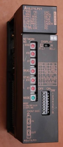
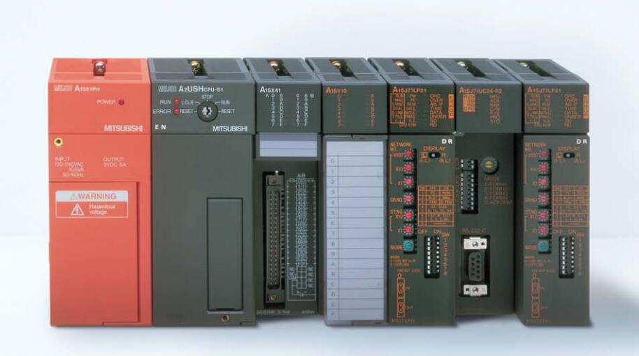
A1SJ71LP21 Market price | A1SJ71LP21 Introduction
- Brand: MITSUBISHI
- Country: JAPAN
- Name: Melsecnet module
- Model: A1SJ71LP21
- Price: U.S.$ 2357.63
MITSUBISHI A1SJ71LP21
A pack of 10.
Applicable models:
AJ65VBTCE - -8 - type.
AJ65VBTCE - -16 - type. Input channel number: 4.
Output channel number: 2.
Occupy I/O points: 64.
A1S63ADA analog input / output combination components can be analog / digital / digital / analog conversion,
The input and output signals can be voltage or current,
Offset and gain can be set and stored.
The length of time required to execute the instruction, the length of the user''s program, the type of instruction, and the speed of the CPU execution are very significant,
Generally, a scanning process, the fault diagnosis time,
Communication time, input sampling and output refresh time is less,
The execution time is accounted for the vast majority of A1SJ71LP21
The response time of PLC is the interval between the time of the change of the external output signal of the PLC and the time of the change of the external output signal which is controlled by it,
Lag time, this is the time constant of the input circuit,
The time constant of the output circuit, the arrangement of the user statement and the use of the instruction,
The cycle scan mode of PLC and the way of PLC to refresh the I/O and so on.
This phenomenon is called the I/O delay time effect. Drive: MR-H_ACN series built-in positioning function.
Rated output: 22KW.
In servo drive speed closed loop,
Rotor speed measurement accuracy is very important to improve the dynamic and static characteristics of the speed control loop.
In order to seek the balance between measurement precision and system cost, incremental photoelectric encoder is generally used as the speed measuring sensor,
The corresponding method is M/T velocity measurement.
Although the M/T measurement method has a certain measurement accuracy and a wide range of measurement,
But this method has its inherent defects,
Mainly includes: the measurement period must be detected at least one complete encoder pulse, limiting the minimum detectable speed.
2 control system for speed control of the timer switch is difficult to maintain synchronization,
Can not guarantee the accuracy of measurement in the situation where the speed change is larger.
Therefore, it is difficult to improve the speed tracking and control performance of servo drive by using the traditional speed loop design method.
A1SJ71LP21 Operation manual/Instructions/Model selection sample download link: /searchDownload.html?Search=A1SJ71LP21&select=5
...more relevant model market price >>>>
Related products
MITSUBISHI
Ethernet module
A1SJ71E71N-B2
10BASE2.
PLC is introduced y the relay
MITSUBISHI
Melsecnet interface module
A1SJ71AP21GE
PLC station distance: 2Km.
Cale type: G
MITSUBISHI
Master control module
A1SJ71T32-S3
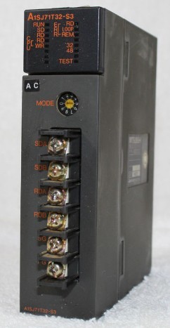
Cale type: twisted pair.
A1SJ71PT32-S3

