LK Automation Limited
Brand Sort:
MITSUBISHI
A1S38HB Market price | A1S38HB Introduction
- Brand: MITSUBISHI
- Country: JAPAN
- Name: floor
- Model: A1S38HB
- Price: U.S.$ 425.42
MITSUBISHI A1S38HB
MITSUBISHI inverter FR-F720 series.
Voltage level: three phase 200V.
Frequency converter capacity: 18.5KW.
When the inverter is running, the starting current and starting torque of the motor are how?
With the operation of the inverter, with the acceleration of the motor to improve the frequency and voltage,
The starting current is limited to 150% below the rated current (according to the different types of aircraft, 125%~200%) A1S38HB
Starting with power frequency power supply, the starting current is 6~7 times of the rated current, therefore, the impact on the mechanical and electrical.
The inverter drive can be smoothly start (start time longer).
The starting current is 1.2~1.5 times of the rated current, and the starting torque is 70%~120% rated torque;
For the inverter with the torque automatic enhancement function, the starting torque is more than 100%, which can start with full load. Superior high efficiency IPM motor.
Output power: 1.5kw.
Rated speed: 1500r/min.
Voltage level: 400V.
IPM motor MM-EFS series can not be used to run the power frequency power.
The total wiring length of the IPM motor shall not exceed 100m.
1 inverters can not connect multiple IPM motors at the same time. Storage capacity: 16MB.
Applicable models: A985 (-V) /A975/A970/A960GOT (-B). RS-232:1, RS-422/485:1.
Transmission speed: 0.3 ~ 19.2kpbs.
Computer connection function.
Printer / peripheral device connection, BASIC language function.
How to choose MITSUBISHI PLC.
MITSUBISHI PLC options include the choice of MITSUBISHI PLC models, capacity, I/O module, power, etc..
MITSUBISHI PLC distribution I/O points and design MITSUBISHI PLC peripheral hardware circuit
Draw the I/O point of the PLC and the input / output device connection diagram or the corresponding table,
This part also can be carried out in second steps.
Design PLC peripheral hardware circuit.
Draw the electrical wiring diagram of the other parts of the system,
Including the main circuit and the control circuit does not enter the PLC, etc..
The electrical schematic diagram of the system composed of I/O PLC connection diagram and PLC peripheral electrical circuit diagram.
So far the system''s hardware electrical circuit has been determined.
A1S38HB Operation manual/Instructions/Model selection sample download link: /searchDownload.html?Search=A1S38HB&select=5
...more relevant model market price >>>>
Related products
MITSUBISHI
Input module
A1SX40
Type of input: DC leakage.
Input points:
MITSUBISHI
High speed counting module
A1SD61
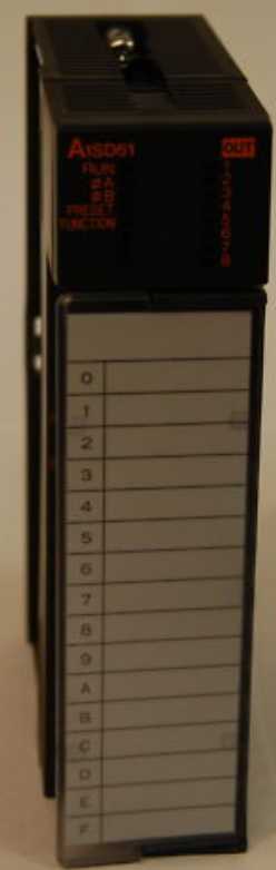
The A1SD61 high speed counting module ca