Brand Sort:
MITSUBISHI
MR-J3-200BS4 Market price | MR-J3-200BS4 Introduction
- Brand: MITSUBISHI
- Country: JAPAN
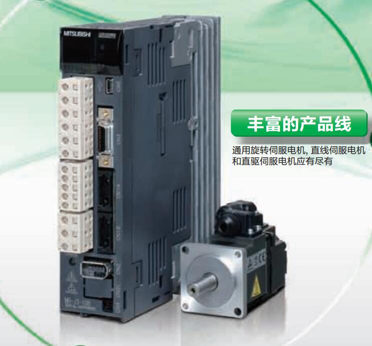
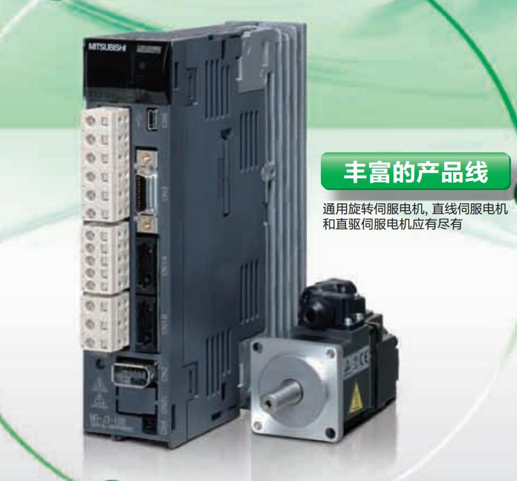
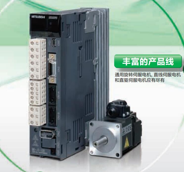
- Name: Integrated drive safety function driver
- Model: MR-J3-200BS4
- Price: 0 >
MITSUBISHI MR-J3-200BS4
Power: 11kw.
Purpose: to suppress the power harmonics.
Improve the power factor, reduce the input side of the high harmonic current.
Make sure that this option is installed in the FR-A820-03800 (75K) and FR-A840-02160 (75K) and above capacity and above capacity.
At the same time the installation options in the use of 75kW and above motor. (the IP55 series has a built-in DC reactor.)
According to the motor power used to select the DC reactor MR-J3-200BS4
(when the inverter capacity is greater than the motor capacity, is still based on the motor capacity to choose.) Type: MR-C type.
Symbol 10A for motor models: HC-PQ23.
Power supply voltage: single phase AC100V.
Drive: servo drive in the development of the premise of the frequency conversion technology,
Current loop in the drive,
Speed loop and position loop (frequency converter without the ring) have carried out a more precise control than the general frequency control technology and algorithm,
In function is also a lot stronger than the traditional servo,
The main point can be precise position control.
The control speed and position are controlled by the pulse sequence transmitted by the upper controller,
The internal algorithm of the driver and the faster and more accurate calculation and better performance of electronic devices to make it more superior to the inverter. Input and output points: 512 points.
Input / output data points: 512 points.
Program capacity: 14K.
Basic command processing speed (LD command) s:0.20.
Optical data communication line function (GI cable).
Integral type: the PLC components are installed together or a few pieces of printed circuit board,
And together with the power supply installed in the casing to form a single overall called the host or the basic unit, small, ultra small PLC using this structure.
Modular: PLC is the basic components of a separate module.
Medium and large PLC used this way. Easy maintenance.
Each scanning process. Focus on the input signal sampling. Focus on the output signal to refresh.
Input refresh process. When the input port is closed,
Program in the implementation phase, the input end of a new state, the new state can not be read.
Only when the program is scanned, the new state is read.
A scan cycle is divided into the input sample, the program execution, the output refresh.
The contents of the component image register are changed with the change of the execution of the program.
The length of the scan cycle is determined by the three.
CPU the speed of executing instructions.
Time of instruction.
Instruction count.
Due to the adoption of centralized sampling.
Centralized output mode.
There exist input / output hysteresis phenomena, i.e., the input / output response delay.
User program storage capacity: it is a measure of how much the user application can store the number of indicators.
Usually in words or K words as units. 16 bit binary number is a word,
Every 1024 words are 1K words. PLC to store instructions and data in words.
General logical operation instructions each account for 1 words. Timer / counter,
Shift instruction accounted for 2 words. Data operation instructions for 2~4.
MR-J3-200BS4 Operation manual/Instructions/Model selection sample download link: /searchDownload.html?Search=MR-J3-200BS4&select=5
...more relevant model market price >>>>
Related products
MITSUBISHI
Universal pulse interface driver
MR-J3-350A

MITSUBISHI motor universal AC servo ampl
MITSUBISHI
Suitable for linear servo motor drive
MR-J3-200B4-RJ004

MITSUBISHI motor universal AC servo ampl
MITSUBISHI
Suitable for linear servo motor drive
MR-J3-200B-RJ004

MITSUBISHI motor universal AC servo ampl
MITSUBISHI
Full closed loop control driver
MR-J3-100B-RJ006

MITSUBISHI motor universal AC servo ampl

