Brand Sort:
MITSUBISHI
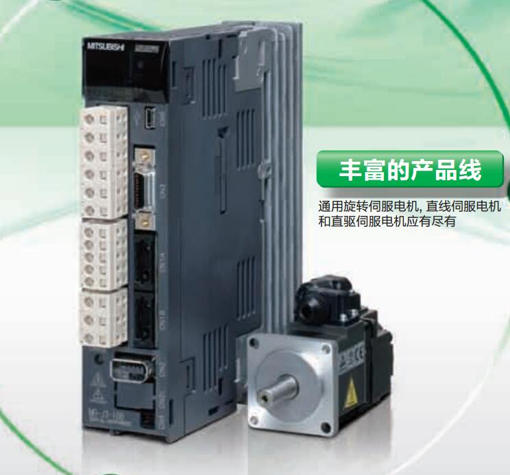
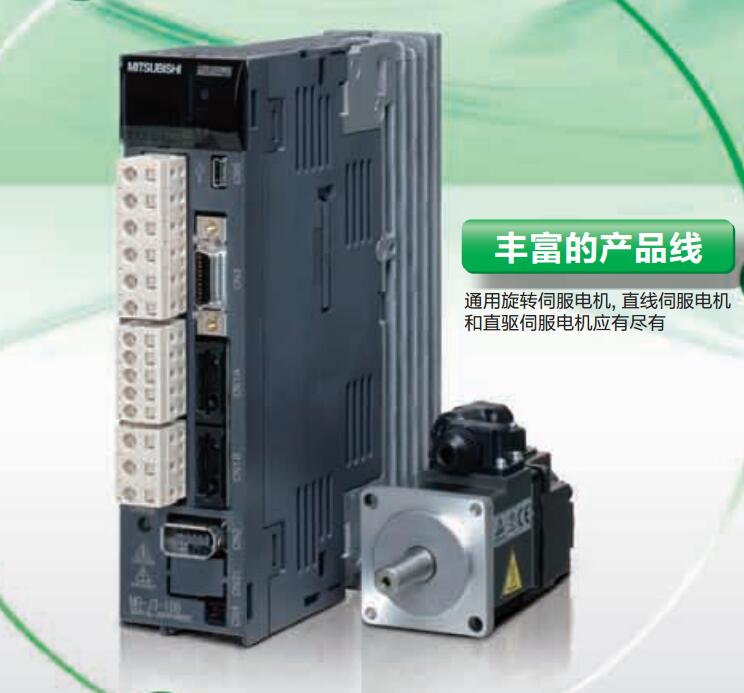
MR-J3-100B4 Market price | MR-J3-100B4 Introduction
- Brand: MITSUBISHI
- Country: JAPAN
- Name: SSCNET type III optical fiber communication driver
- Model: MR-J3-100B4
- Price: 0 >
MITSUBISHI MR-J3-100B4
Fiber length: 0.15 meters.
SSCNET III cables (standard optical fiber used in control cabinet).
Joints for CN1A and CN1B. Input type: DC input, negative public end.
Input points: 16 points.
Enter the response time: 1.5ms the following.
Rated input voltage / current: DC24V/5mA.
External connection: 4 wire.
Fast connector type.
Simple wiring through quick connector.
Can be installed along the 6 direction MR-J3-100B4
MITSUBISHI PLC program simulation debugging
The basic idea of program simulation debugging is,
In order to facilitate the form of simulation to generate the actual state of the scene,
Create the necessary environmental conditions for the operation of the program.
Depending on the way the field signals are generated,
The simulation debugging has two forms of hardware simulation and software simulation. SI/QSI/H-PCF/ wide range H-PCF fiber optic cable.
Double loop.
PC inter network (management station / station) / remote I/O network (remote control station).
How to choose MITSUBISHI PLC.
MITSUBISHI PLC options include the choice of MITSUBISHI PLC models, capacity, I/O module, power, etc..
MITSUBISHI PLC distribution I/O points and design MITSUBISHI PLC peripheral hardware circuit
Draw the I/O point of the PLC and the input / output device connection diagram or the corresponding table,
This part also can be carried out in second steps.
Design PLC peripheral hardware circuit.
Draw the electrical wiring diagram of the other parts of the system,
Including the main circuit and the control circuit does not enter the PLC, etc..
The electrical schematic diagram of the system composed of I/O PLC connection diagram and PLC peripheral electrical circuit diagram.
So far the system''s hardware electrical circuit has been determined. A1SS91 is used to insert a fixed control program in front of the user program to monitor the specific Y output.
Monitoring is carried out only when the CPU is in a state of running or stopping, and the monitoring failure is monitored in the suspended state.
When using this module, you can output from the I/O bus error contact or output from the running contact or the general contact output,
DC5V check can also be performed.
The popularization and application of PLC programming has been developed rapidly in our country,
It has been widely used in all kinds of mechanical equipment and production process of electrical control devices,
All walks of life have emerged a large number of application of PLC transformation of the results of the equipment.
Understand the working principle of PLC, have the ability to design, debug and maintain the PLC control system,
Has become the basic requirements of modern industry for electrical technicians and engineering students.
The instruction list programming language is a programming language similar to assembly language mnemonic,
As well as assembly language by the operation code and the number of operations.
In the case of the computer for the PLC handheld programmer compile user program.
At the same time, the programming language of the instruction list corresponds to the ladder diagram programming language,
In PLC programming software can be converted to each other. Figure 3 is the instruction sheet corresponding to the ladder diagram of figure 2PLC.
The characteristics of instruction table programming language is used to represent mnemonic operation function,
Easy to remember, easy to grasp;
In the handheld programmer on the keyboard using the mnemonic representation, easy to operate, can be programmed in computer;
There is a one-to-one correspondence between the ladder diagram and the ladder diagram. Its characteristics are basically consistent with the ladder diagram language.
MR-J3-100B4 Operation manual/Instructions/Model selection sample download link: /searchDownload.html?Search=MR-J3-100B4&select=5
...more relevant model market price >>>>
Related products
MITSUBISHI
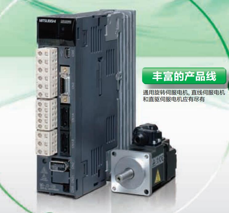
CC-Link communication driver
MR-J3-60T
MITSUBISHI motor universal AC servo ampl
MITSUBISHI
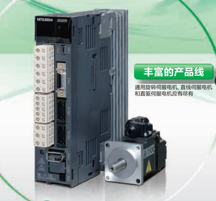
Universal pulse interface driver
MR-J3-10A1
MITSUBISHI motor universal AC servo ampl
MITSUBISHI
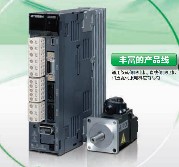
Integrated drive safety function driver
MR-J3-350BS
MITSUBISHI motor universal AC servo ampl
MITSUBISHI
CC-Link communication driver
MR-J3-700T4
MITSUBISHI motor universal AC servo ampl

