Brand Sort:
MITSUBISHI
HC-SF702B Market price | HC-SF702B Introduction
- Brand: MITSUBISHI
- Country: JAPAN
- Name: Medium inertia medium capacity motor
- Model: HC-SF702B
- Price: 0 >
MITSUBISHI HC-SF702B
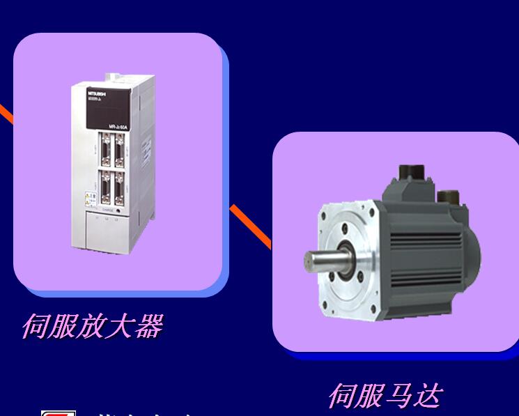
MITSUBISHI general purpose AC servo amplifier MR-J2 series.
Rated output: 0.6kw.
Interface: general purpose interface.
Voltage: single phase AC200V.
MITSUBISHI servo system in the MITSUBISHI servo amplifier is widely used,
It can not only be used in the high precision position control and speed control of the working machinery and general industrial machinery,
Can also be used in the field of speed control and tension control HC-SF702B
By installing a personal computer with a servo setting software, the parameters setting, trial run, state display, and gain adjustment are performed.
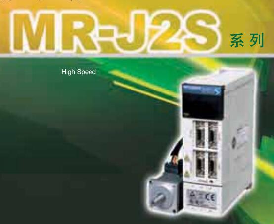
MITSUBISHI servo system MR-J2S column is developed on the basis of the servo MR-J2 series with a higher performance and more features of the MITSUBISHI servo system,
The control modes are position control, speed control and torque control, as well as the switching control mode among them. DC input points: 4 points.
Input voltage and current: 7mA, DC24V.
Input response time: 10ms.
4 point /1 a public side.
Positive / negative sharing.
Output points: 4 points.
Output voltage and current: DC24V/AC240V, 2A/1 point, 8A/1 common end.
Output response time: 12ms.
4 point /1 a public side.
Output form: relay.
24 point terminal station.
MITSUBISHI PLC protection and chain procedures.
Protection and chain is an indispensable part of the program, must be carefully considered.
It can avoid the control logic confusion caused by illegal operations.
MITSUBISHI PLC initialization procedure. After MITSUBISHI PLC on power, the general need to do some of the initial operation,
In order to start making necessary preparations, to avoid the wrong operation of the system.
The main contents of the initialization program are: to some data area, counter and so on,
Data needed to restore some of the data area,
Set or reset some relays,
For some initial state display, etc..
MITSUBISHI PLC program simulation debugging
The basic idea of program simulation debugging is,
In order to facilitate the form of simulation to generate the actual state of the scene,
Create the necessary environmental conditions for the operation of the program.
Depending on the way the field signals are generated,
The simulation debugging has two forms of hardware simulation and software simulation.
HC-SF702B Operation manual/Instructions/Model selection sample download link: /searchDownload.html?Search=HC-SF702B&select=5
...more relevant model market price >>>>
Related products
MITSUBISHI
Medium inertia power motor
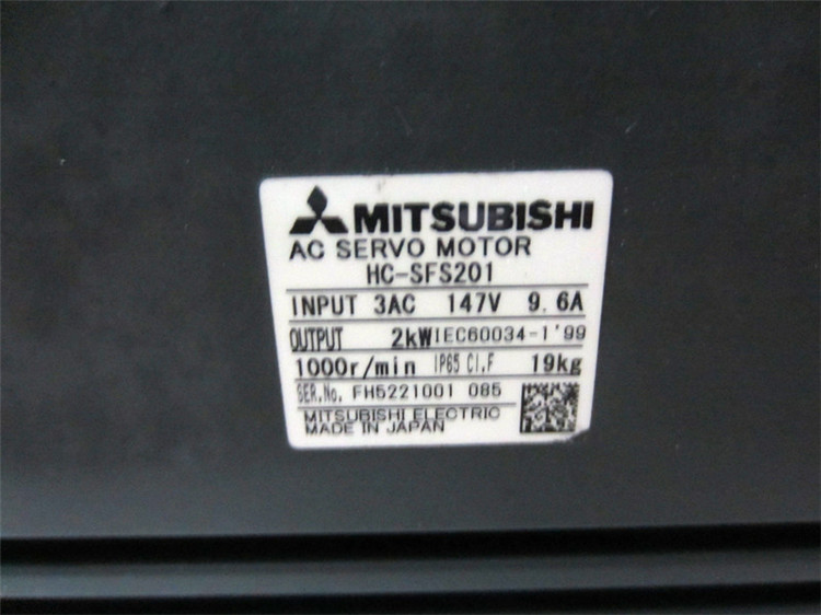
HC-SFS201

Motor series: medium inertia, medium pow
MITSUBISHI
Medium inertia power motor
HC-SFS1024

Motor series: medium inertia, medium pow
MITSUBISHI
Medium inertia power motor
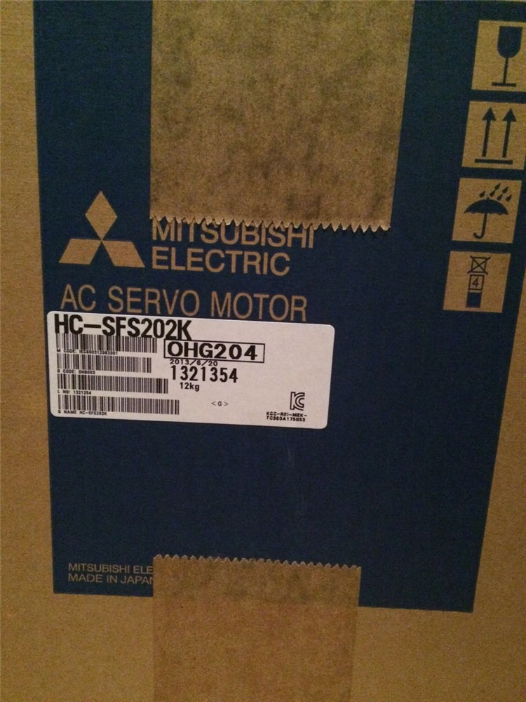
HC-SFS202K

Motor series: medium inertia, medium pow
MITSUBISHI
Medium inertia medium capacity motor
HC-SF203

Motor series: medium inertia, medium cap

