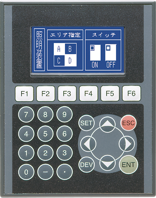
Brand Sort:
MITSUBISHI
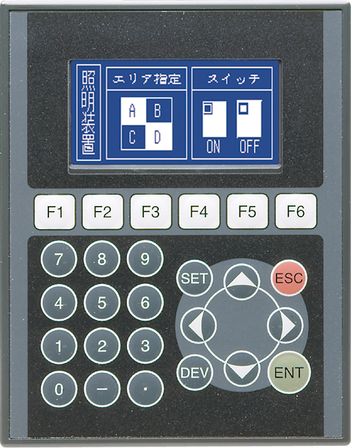
F920GOT-BBD-5-K Market price | F920GOT-BBD-5-K Introduction
- Brand: MITSUBISHI
- Country: JAPAN
- Name: 2.6 Inch Touch Screen
- Model: F920GOT-BBD-5-K
- Price: 0 >
MITSUBISHI F920GOT-BBD-5-K
"Maximum control axis: 2 axis.
Connection mode with servo amplifier: SSCNET III /H connection type.
The maximum distance between the drive units: 100m.
Operation cycle: 0.88ms.
Interpolation function: linear interpolation (maximum 4 axis), 2 axis arc interpolation.
Color signal: 2 points.
Color detecting set: 4 set.
Even the long distance wiring can be flexible.
The use of fiber optic cable, with high speed, high performance, high reliability of the servo system controller network F920GOT-BBD-5-K
In addition to the traditional positioning control, but also to support speed / torque control and synchronous control.
Use simple movement module setup tool",
Can easily perform positioning settings, monitoring and debugging, etc..
In addition, the data can be collected and displayed synchronously with the motion controller.
SSCNET III /H connection to save the wiring, the maximum distance between the station up to 100m,
Absolute position system can be easily supported.
The upper limit limit switch, the lower limit switch and the near point block signal are input by the servo amplifier,
Thus greatly reducing wiring.
In addition to positioning control and speed control, but also to perform synchronization control, cam control, torque control, touch pressure control, etc..
Positioning module (QD75MH) of the project and the sequence of the previous model is highly compatible with the old model,
The project can be easily applied to the simple motion module (QD77MS). "GI fiber optic cable.
Dual loop for Q mode.
PC inter network (management station / station) / remote I/O network (remote control station).
How to choose MITSUBISHI PLC.
MITSUBISHI PLC options include the choice of MITSUBISHI PLC models, capacity, I/O module, power, etc..
MITSUBISHI PLC distribution I/O points and design MITSUBISHI PLC peripheral hardware circuit
Draw the I/O point of the PLC and the input / output device connection diagram or the corresponding table,
This part also can be carried out in second steps.
Design PLC peripheral hardware circuit.
Draw the electrical wiring diagram of the other parts of the system,
Including the main circuit and the control circuit does not enter the PLC, etc..
The electrical schematic diagram of the system composed of I/O PLC connection diagram and PLC peripheral electrical circuit diagram.
So far the system''s hardware electrical circuit has been determined.
F920GOT-BBD-5-K Operation manual/Instructions/Model selection sample download link: /searchDownload.html?Search=F920GOT-BBD-5-K&select=5
...more relevant model market price >>>>
Related products
MITSUBISHI
2.6 Inch Touch Screen
F920GOT-BBD-5-K-E
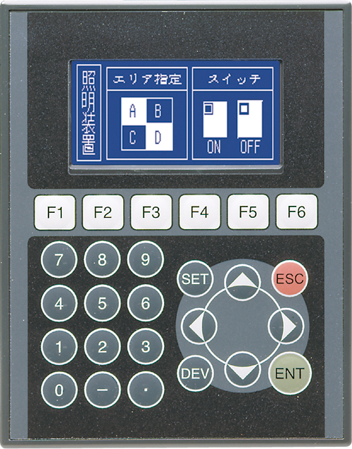
Series Name: F920GOT with uttons, with
MITSUBISHI
2.6 Inch Touch Screen
F920GOT-BBD-K-E
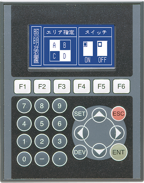
Series Name: F920GOT with uttons, with
MITSUBISHI
2.6 Inch Touch Screen
F920GOT-BBD-K-C
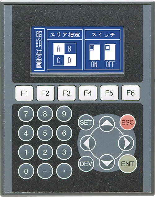
Series Name: F920GOT with uttons, with
MITSUBISHI
2.6 Inch Touch Screen
F920GOT-BBD-5-K-C
Series Name: F920GOT with uttons, with

