 LK Automation Limited
Download Sort:
MITSUBISHI
MITSUBISHI AJ65VBTCE2-16T datasheet PDF catalog AJ65VBTCE2-16T PDF datasheet
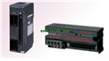
Product model: AJ65VBTCE2-16T
Name: Sensor connector type transistor output module
Brand: MITSUBISHI
Sort: PDF datasheet
File language: English
Download link: MITSUBISHI AJ65VBTCE2-16T PDF datasheet
Input type: DC input, positive common end.
Input points: 16 points.
Enter the response time: 1.5ms the following.
Rated input voltage / current: DC24V/5mA.
External connection: 3 wire.
Sensor connector type (E-CON type).
Using industry standard E-CON type.
Simple wiring through sensor connector.
When installing the module can choose to use the DIN guide rail or screw mounting AJ65VBTCE2-16T datasheet PDF catalog AJ65VBTCE2-16T PDF datasheet AJ65VBTCE2-16T
3 wire sensor input. Description: GI type optical fiber cable with (combination of 2 sets of use), the maximum number of connections: 2, the longest transmission distance: 2000m.
Spare 5 products for different purposes.
Thin waterproof type relay hub.
Extension of star type wiring and main line length, waterproof structure AJ65VBTCE2-16T datasheet PDF catalog AJ65VBTCE2-16T PDF datasheet.
Spring clip terminal type relay hub.
Star type wiring, length of the main line, spring clamping terminal table type.
Relay appliance (T branch) unit.
Extension of T type branch and trunk length.
Relay unit in light.
In the presence of interference in the environment of the wiring, the length of the trunk line.
Relay unit in space light.
Communication between linear moving bodies. RS-232:1 channel, RS-422:1 channel AJ65VBTCE2-16T datasheet PDF catalog AJ65VBTCE2-16T PDF datasheet.
BASIC program mode (A3MCPU corresponding): BASIC console interface to use.
Sequential program mode (program controller CPU correspondence): non sequential computer connection interface and use.
How to choose MITSUBISHI PLC.
MITSUBISHI PLC options include the choice of MITSUBISHI PLC models, capacity, I/O module, power, etc..
MITSUBISHI PLC distribution I/O points and design MITSUBISHI PLC peripheral hardware circuit
Draw the I/O point of the PLC and the input / output device connection diagram or the corresponding table,
This part also can be carried out in second steps.
Design PLC peripheral hardware circuit.
Draw the electrical wiring diagram of the other parts of the system,
Including the main circuit and the control circuit does not enter the PLC, etc AJ65VBTCE2-16T datasheet PDF catalog AJ65VBTCE2-16T PDF datasheet. .
The electrical schematic diagram of the system compoosed of I/O PLC connection diagram and PLC peripheral electrical circuit diagram AJ65VBTCE2-16T datasheet PDF catalog AJ65VBTCE2-16T PDF datasheet.
So far the system''s hardware electrical circuit has been determined.
Related products
MITSUBISHI
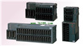
40 pin connector type DC input / transistor output module
AJ65VBTCF1-32DT1
Input type: DC input, positive pulic en
MITSUBISHI
Fast connector type transistor output module
AJ65VBTCU2-8T
Output type: transistor output, drain ty
MITSUBISHI
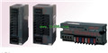
Sensor connector type DC input / transistor output module
AJ65VBTCE32-32DT
Input type: DC input, positive common en
MITSUBISHI
Sensor connector type transistor output module
AJ65VBTCE2-16T

Output type: transistor output, drain ty