 LK Automation Limited
Download Sort:
MITSUBISHI
MITSUBISHI A9GT-70LTT datasheet PDF catalog A9GT-70LTT PDF datasheet
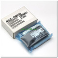
Product model: A9GT-70LTT
Name: Backlight
Brand: MITSUBISHI
Sort: PDF datasheet
File language: English
Download link: MITSUBISHI A9GT-70LTT PDF datasheet
Number of channels: RS422, 1 channel
.
Configuration of master / local station,
In addition to the other site network with different CC-Link in addition to the main station and the remote station configuration can also be the main station and the local station configuration.
A local PLC can communicate with the master station PLC and other remote workstations A9GT-70LTT datasheet PDF catalog A9GT-70LTT PDF datasheet A9GT-70LTT
MITSUBISHI PLC online debugging.
On-line debugging is the process that will through the simulation debugging to further carry on the on-line unification to adjust.
On-line debugging process should be step by step,
From MITSUBISHI PLC only connected to the input device, and then connect the output device, and then connect to the actual load and so on and so on step by step A9GT-70LTT datasheet PDF catalog A9GT-70LTT PDF datasheet.
If you do not meet the requirements, the hardware and procedures for adjustment.
Usually only need to modify the part of the program can be.
MITSUBISHI PLC hardware implementation
Hardware implementation is mainly for the control cabinet and other hardware design and field construction.
Design control cabinet and the operating table and other parts of the electrical wiring diagram and wiring diagram A9GT-70LTT datasheet PDF catalog A9GT-70LTT PDF datasheet.
Electrical interconnection diagram of each part of the design system.
According to the construction drawings of the site wiring, and carry out a detailed inspection.
Because the program design and hardware implementation can be carried out at the same time,
So the design cycle of the MITSUBISHI PLC control system can be greatly reduced. Type of input: DC leakage.
Input points: 32 points.
Input voltage: DC24.
Input current: 7mA.
Connection mode: terminal row.
Common common point: 32.
Functional block diagram language is a kind of PLC programming language, which is similar to digital logic circuit.
The function module is used to represent the function of the module,
Different function modules have different functions.
Functional module figure programming language features: functional block diagram programming language is characterized by a functional module for the unit,
Analysis and understanding of the control scheme is simple and easy: function module iss to use graphical form of expression,
Intuitive, for a digital logic circuit based on the design of the staff is very easy to master the programming;
Control system with complex scale and coomplex control logic,
Because the function module diagram can clearly express the function relation, the programming debugging time is greatly reduced A9GT-70LTT datasheet PDF catalog A9GT-70LTT PDF datasheet A9GT-70LTT datasheet PDF catalog A9GT-70LTT PDF datasheet.
Related products


MITSUBISHI
Memory card
A9GT-FNB1M
Optional features of memory card A/FX c
MITSUBISHI
Backlight
A9GT-50LT
STN color / monochrome LCD man-machine i