Download Sort:
MITSUBISHI
MITSUBISHI A9GT-QBUS2S Manual A9GT-QBUS2S User's Manual
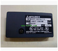
Product model: A9GT-QBUS2S
Name: Multidrop Bus connection communication board
Brand: MITSUBISHI
Sort: User's Manual
File language: English
Download link: MITSUBISHI A9GT-QBUS2S User's Manual
MITSUBISHI PLC hardware implementation
Hardware implementation is mainly for the control cabinet and other hardware design and field construction.
Design control cabinet and the operating table and other parts of the electrical wiring diagram and wiring diagram.
Electrical interconnection diagram of each part of the design system A9GT-QBUS2S Manual A9GT-QBUS2S User's Manual.
According to the construction drawings of the site wiring, and carry out a detailed inspection A9GT-QBUS2S
Because the program design and hardware implementation can be carried out at the same time,
So the design cycle of the MITSUBISHI PLC control system can be greatly reduced. A0J2 56.
Input / output unit 2
MITSUBISHI PLC program simulation debugging
The basic idea of program simulation debugging is,
In order to facilitate the form of simulation to generate the actual state of the scene,
Create the necessary environmental conditions for the operation of the program A9GT-QBUS2S Manual A9GT-QBUS2S User's Manual.
Depending on the way the field signals are generated,
The simulation debugging has two forms of hardware simulation and software simulation. Storage capacity: 32MB.
Applicable models: A985 (-V) /A975/A970/A960GOT (-B) A9GT-QBUS2S Manual A9GT-QBUS2S User's Manual. Enter 8 points.
7mA DC24V.
Response time: 12ms.
8 positive, 1 public to reduce the public in common use.
Output 8 points.
DC24V/AC240V, 2A/1 point, 8A/1 common.
Response time: 12ms.
8 point 1 public 20 point terminal.
PLC is introduced by the relay control technology after the development of micro processing technology,
Can be easily and reliably used for switching control.
As the analog quantity can be converted into digital quantity, the number of digital quantity is just a number of switching value,
Therefore, after the conversion of analog, PLC can also be reliable for processing control.
Because the continuous production process often has the analog quantity, the analog quantity control is sometimes called process control.
Analog quantity is not electricity, and PLC can only handle digital quantity, quantity of electricity.
All to realize the conversion between them to have the sensor, the analog quantity into a number of power.
If this power is not standard, but also through the transmitter,
The non-standard power into a standard electrical signal, such as 1-5V, 4-20mA, 0-10V, etc..
At the same time, there is also an analog input unit (A/D),
Transform these standard electrical signals into digital signaals,
The analog output unit (D/A), in order to transform the digital quantity after PLC processing into analog quantity -- standard electric signal A9GT-QBUS2S Manual A9GT-QBUS2S User's Manual.
So the standard telecommunication number, the conversiion between the number of operations to use a variety of computing A9GT-QBUS2S Manual A9GT-QBUS2S User's Manual.
This requires the resolution of the analog unit and the standard electrical signal.
Related products
MITSUBISHI
Serial communication board
A9GT-50WRS4

RS-422 connection QnA/A/FXCPU direct co
MITSUBISHI
Memory card
A9GT-FNB8M

Optional features of memory card A/FX c
MITSUBISHI
Bus connection unit
A9GT-BUS2SU

QnA/ACPU us connection.
2 joint.
Applic
MITSUBISHI
Backlight
A9GT-70LTT

TFT color LCD touch screen to replace th
