LK Automation Limited
Download Sort:
MITSUBISHI
MITSUBISHI A953GOT-SBD-M3-H datasheet PDF catalog A953GOT-SBD-M3-H PDF datasheet
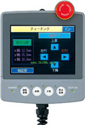
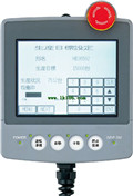
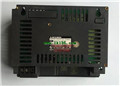
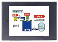
Product model: A953GOT-SBD-M3-H
Name: Touch screen
Brand: MITSUBISHI
Sort: PDF datasheet
File language: English
Download link: MITSUBISHI A953GOT-SBD-M3-H PDF datasheet
Enter 8 points.
7mA DC24V.
Response time: 12ms.
8 positive, 1 public to reduce the public in common use.
Output 8 points.
DC24V/AC240V, 2A/1 point, 8A/1 common.
Response time: 12ms.
8 point 1 public 20 point terminal.
PLC is introduced by the relay control technology after the development of micro processing technology,
Can be easily and reliably used for switching control A953GOT-SBD-M3-H datasheet PDF catalog A953GOT-SBD-M3-H PDF datasheet A953GOT-SBD-M3-H
As the analog quantity can be converted into digital quantity, the number of digital quantity is just a number of switching value,
Therefore, after the conversion of analog, PLC can also be reliable for processing control.
Because the continuous production process often has the analog quantity, the analog quantity control is sometimes called process control A953GOT-SBD-M3-H datasheet PDF catalog A953GOT-SBD-M3-H PDF datasheet.
Analog quantity is not electricity, and PLC can only handle digital quantity, quantity of electricity.
All to realize the conversion between them to have the sensor, the analog quantity into a number of power.
If this power is not standard, but also through the transmitter,
The non-standard power into a standard electrical signal, such as 1-5V, 4-20mA, 0-10V, etc A953GOT-SBD-M3-H datasheet PDF catalog A953GOT-SBD-M3-H PDF datasheet. .
At the same time, there is also an analog input unit (A/D),
Transform these standard electrical signals into digital signals,
The analog output unit (D/A), in order to transform the digital quantity after PLC processing into analog quantity -- standard electric signal.
So the standard telecommunication number, the conversion between the number of operations to use a variety of computing.
This requires the resolution of the analog unit and the standard electrical signal. 2 channels.
3 wire platinum measuring antibodies (Pt100, JPt100).
Transform speed: 40ms/1 channel.
20 point terminal station.
The popularization and application of PLC programming has been developed rapidly in our country,
It has been widely used in all kinds of mechanical equipment and production process of electrical control devices,
All walks of life have emerged a large number of application of PLC transformation of the results of the equipment.
Understand the working principle of PLC, have the ability to design, debug and maintain the PLC control system,
Has become the basic requirements of modern industry for electrical technicians and engineering students.
PLC user program is designed according to the control system of the process control requirements,
PLC programming language through the preparation of specifications, in accordance with the actual needs of the use of the function to design.
As long as the user can master some kind of standard programming language,
To be able to use PLC in the control system,
To achieve a variety of automatic control functions.
The instruction list programming language is a programming language similar to assembly language mnemonic,
As well as assembly language by the operation code and the number of operations.
In the case of the computer for the PLC handheld programmer compile user program.
At the same time, the programming language of the instruction list corresponds to the ladder diagram programming language,
In PLC programming software can be converted to each other. Figure 3 is the instruction sheet corresponding to the ladder diagram of figure 2PLC.
The characteristics of instruction table programming language is used to represent mnemonic operation function,
Easy to remember, easy to grasp;
In the handheld programmer on the keyboard using the mnemonic representation, easy to operate, can be programmed in computer;
There is a one-to-one correspondence between the ladder diagram and the ladder diagram. Its characteristics are basically consistent with the ladder diagram language.
Functional block diagram language is a kind of PLC programming language, which is similar to digital logic circuit.
The function module is used to represent the function of the module,
Different function modules have different functions.
Functional module figure programming language features: functional block diagram programming language is characterized by a functional module for the unit,
Analysis and understanding of the control scheme is simple and easy: function module is to use grapphical form of expression,
Intuitive, for a digital logic circuit based on the design of the staff is very easy to master the programming;
Control system with complex scale and coomplex control logic,
Because the function module diagram can clearly express the function relation, the programming debugging time is greatly reduced A953GOT-SBD-M3-H datasheet PDF catalog A953GOT-SBD-M3-H PDF datasheet A953GOT-SBD-M3-H datasheet PDF catalog A953GOT-SBD-M3-H PDF datasheet.
Related products
MITSUBISHI
6 inch man machine interface
A953GOT-LBD
Series Name: A953GOT.
Size: 6 inches.
Re
MITSUBISHI
6 inch man machine interface
A953GOT-TBD
Series Name: A953GOT.
Size: 6 inches.
Re