 LK Automation Limited
Download Sort:
MITSUBISHI
MITSUBISHI A2NCPUP21-S4 datasheet PDF catalog A2NCPUP21-S4 PDF datasheet
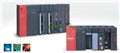
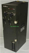
Product model: A2NCPUP21-S4
Name: CPU unit
Brand: MITSUBISHI
Sort: PDF datasheet
File language: English
Download link: MITSUBISHI A2NCPUP21-S4 PDF datasheet
Cable length: 3 meters.
Long distance CPU extension cable.
For QnA/ACPU/ motion control and GOT connection. Type of input: DC source.
Input points: 32 points.
Input voltage: 5/12.
Input current: 1.2/3.3mA.
Connection mode: terminal row.
Common common point: 32.
Functional block diagram language is a kind of PLC programming language, which is similar to digital logic circuit A2NCPUP21-S4 datasheet PDF catalog A2NCPUP21-S4 PDF datasheet A2NCPUP21-S4
The function module is used to represent the function of the module,
Different function modules have different functions.
Functional module figure programming language features: functional block diagram programming language is characterized by a functional module for the unit,
Analysis and understanding of the control scheme is simple and easy: function module is to use graphical form of expression,
Intuitive, for a digital logic circuit based on the design of the staff is very easy to master the programming;
Control system with complex scale and complex control logic,
Because the function module diagram can clearly express the function relation, the programming debugging time is greatly reduced A2NCPUP21-S4 datasheet PDF catalog A2NCPUP21-S4 PDF datasheet. Cable 1.2m for the expansion of the floor, the expansion of a floor for every 1 units A2NCPUP21-S4 datasheet PDF catalog A2NCPUP21-S4 PDF datasheet. There are many A6TB models to different types of matching with the I/O module.
The cable can be connected to the I/O module of 32 points or 64 points by using the terminal row of the wire in advance.
These cables have a variety of lengths to be selected, so that
Using the module wiring and terminal is not only connected with the connector. Analog channel: 4 channels.
Input / output (resolution): 0 ~ 4000.
Conversion speed: 100ms/4 channel.
Analog module installation.
Power supply: AC170V ~ 264V.
According to the control requirements of the system, using the appropriate design method to design MITSUBISHI PLC program.
Procedures to meet the requirements of system control as the main line,
Write one by one to achieve the control function or the sub task of the program,
Gradually improve the functions specified by the system.
MITSUBISHI PLC detection, fault diagnosis and display and other procedures.
These procedures are relatively independent, generally in the basic completion of the program design and then add.
Hardware simulation method is to use a number of hardware equipment to simulate the generation of the signal,
The signals are connected to the input end of the PLC system in a hard wired way, and the timeliness is strong.
Software simulatiion method is in the MITSUBISHI PLC in the preparation of a set of simulation program,
The simulation provides the field signal, which is simple and easy to operate, but it is not easy too guarantee the timeliness A2NCPUP21-S4 datasheet PDF catalog A2NCPUP21-S4 PDF datasheet A2NCPUP21-S4 datasheet PDF catalog A2NCPUP21-S4 PDF datasheet.
Simulation of the process of debugging, debugging method can be used to segment, and the monitoring function of programmer.
Related products
MITSUBISHI
CPU unit
A2NCPUP21-S4
Input and output points: 1024 points.
In
MITSUBISHI
CPU unit
A2NCPU
Input and output points: 512 points.
Inp
MITSUBISHI
CPU unit
A2NCPUP21-S1
Input and output points: 1024 points.
In
MITSUBISHI
CPU unit
A2ACPUP21-S4

Input and output points: 1024 points.
In