 LK Automation Limited
Download Sort:
MITSUBISHI
MITSUBISHI A2ACPUP21-S4 datasheet PDF catalog A2ACPUP21-S4 PDF datasheet
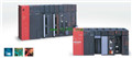
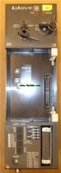
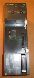
Product model: A2ACPUP21-S4
Name: CPU unit
Brand: MITSUBISHI
Sort: PDF datasheet
File language: English
Download link: MITSUBISHI A2ACPUP21-S4 PDF datasheet
MITSUBISHI PLC online debugging.
On-line debugging is the process that will through the simulation debugging to further carry on the on-line unification to adjust.
On-line debugging process should be step by step,
From MITSUBISHI PLC only connected to the input device, and then connect the output device, and then connect to the actual load and so on and so on step by step A2ACPUP21-S4 datasheet PDF catalog A2ACPUP21-S4 PDF datasheet A2ACPUP21-S4
If you do not meet the requirements, the hardware and procedures for adjustment.
Usually only need to modify the part of the program can be. Input type: DC input, positive public end / negative public end.
Input points: 16 points.
Enter the response time: 1.5ms the following.
Rated input voltage / current: DC24V/5mA.
Output form: transistor output, leakage type A2ACPUP21-S4 datasheet PDF catalog A2ACPUP21-S4 PDF datasheet.
Output points: 16 points.
OFF leakage current: 0.1mA.
Output protection function.
Rated load voltage / current: DC12V/DC24V/0.1A.
External connection: 1 line /1 line type.
40 pin connector type (FCN connector type).
Through the 40 pin connector type (FCN connector type) can be connected to a variety of devices.
Can be installed along the 6 direction.
Hardware simulation method is to use a number of hardware equipment to simulate the generation of the signal,
The signals are connected to the input end of the PLC system in a hard wired way, and the timeliness is strong A2ACPUP21-S4 datasheet PDF catalog A2ACPUP21-S4 PDF datasheet.
Software simulation method is in the MITSUBISHI PLC in the preparation of a set of simulation program,
The simulation provides the field signal, which is simple and easy to operate, but it is not easy to guarantee the timeliness.
Simulation of the process of debugging, debugging method can be used to segment, and the monitoring function of programmer. Cable 3M for the expansion of the floor, the expansion of a floor for every 1 units.Extension cable.
Length: 2000mm. 3C-2V/5C-2V coaxial cable.
Double loop.
Remote I/O network (remote control station).
How to choose MITSUBISHI PLC.
MITSUBISHI PLC options include the choice of MITSUBISHI PLC models, capacity, I/O module, power, etc..
MITSUBISHI PLC distribution I/O points and design MITSUBISHI PLC peripheral hardware circuit
Draw the I/O point of the PLC and the input / output device connection diagram or the corresponding table,
This part also can be carried out in second steps.
Design PLC peripheral hardware circuit.
Draw the electriical wiring diagram of the other parts of the system,
Including the main circuit and the control circuit does not enter the PLC, etc A2ACPUP21-S4 datasheet PDF catalog A2ACPUP21-S4 PDF datasheet. .
The electrical schematic diagram of the system compoosed of I/O PLC connection diagram and PLC peripheral electrical circuit diagram A2ACPUP21-S4 datasheet PDF catalog A2ACPUP21-S4 PDF datasheet.
So far the system''s hardware electrical circuit has been determined.
Related products
MITSUBISHI
CPU unit
A2ACPUP21-S3
Input and output points: 512 points.
Inp
MITSUBISHI
CPU unit
A2ACPUR21-S1
Input and output points: 1024 points.
In
MITSUBISHI
CPU unit
A2ACPUP21-S4

Input and output points: 1024 points.
In
MITSUBISHI
CPU unit
A2ACPUP21
Input and output points: 512 points.
Inp