Download Sort:
MITSUBISHI
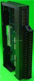
MITSUBISHI AY51 Manual AY51 User's Manual
Product model: AY51
Name: I/O Module
Brand: MITSUBISHI
Sort: User's Manual
File language: English
Download link: MITSUBISHI AY51 User's Manual
RS-232:1, RS-422/485:1.
Transmission speed: 0.3 ~ 19.2kpbs.
Computer connection function.
Printer / peripheral device connection, BASIC language function.
How to choose MITSUBISHI PLC.
MITSUBISHI PLC options include the choice of MITSUBISHI PLC models, capacity, I/O module, power, etc..
MITSUBISHI PLC distribution I/O points and design MITSUBISHI PLC peripheral hardware circuit
Draw the I/O point of the PLC and the input / output device connection diagram or the corresponding table,
This part also can be carried out in second steps AY51 Manual AY51 User's Manual AY51
Design PLC peripheral hardware circuit.
Draw the electrical wiring diagram of the other parts of the system,
Including the main circuit and the control circuit does not enter the PLC, etc AY51 Manual AY51 User's Manual. .
The electrical schematic diagram of the system composed of I/O PLC connection diagram and PLC peripheral electrical circuit diagram.
So far the system''s hardware electrical circuit has been determined. Input type: DC input, positive public end / negative public end.
Input points: 32 points.
Enter the response time: 0.2ms the following.
Rated input voltage / current: DC24V/5mA AY51 Manual AY51 User's Manual.
External connection: 1 wire.
According to the external connection mode and the external equipment input and output specifications,
Choose from a rich product lineup.
Finger protection through the upper part of the terminal,
The human body will not be exposed to live parts,
Therefore, the terminal station type remote I/O module can be directly mounted to the machine tool. 3C-2V/5C-2V coaxial dual ring remote I/O network (remote I/O station).
Q mode.
When the programmer input programinto the user program memory,
Then CPU according to the function of the system (the system program memory to explain the compiler),
Translate the user program into PLC internally recognized by the user to compile the program.
Input status and input information input from the input interface,
CPU will be stored in the working data memory or in the input image register.
And then combine the data and the program with CPU.
The result is stored in the output image register or the working data memory,
And then output to the output interface, control the external drive.
Semiconductor circuit with memory function.
System program memory and user memory.
System program memory for storing system program,
Including management procedures, monitoring procedures, as well as the user program to do the coompiler to compile the process of interpretation AY51 Manual AY51 User's Manual.
Read only memory. Manufacturers use, content can not be changed, power does not disappear.
User memory: user program storage area and work data storage area.
Composed of random access memory (RAM) AY51 Manual AY51 User's Manual. User use.
Power cut off. Commonly used efficient lithium battery as a backup power supply, life is generally 3~5 years.
Related products
MITSUBISHI
Relay output module
AY11EEU

Output points: 16 points.
Voltage: DC24V
MITSUBISHI
Relay output module
AY11

Output points: 16 points.
Voltage: DC24V
MITSUBISHI
CMOS TTL output module
AY71

Output points: 32 points.
Voltage: DC5/1
MITSUBISHI
Transistor output module
AY40P

Output points: 16 points.
Voltage: DC12/
