 LK Automation Limited
Download Sort:
MITSUBISHI
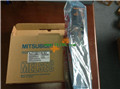
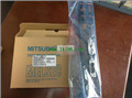
MITSUBISHI AJ71QE71-B5 Hardware Manual AJ71QE71-B5 User's Manual
Product model: AJ71QE71-B5
Name: Ethernet Interface Module
Brand: MITSUBISHI
Sort: Hardware User's Manual
File language: English
Download link: MITSUBISHI AJ71QE71-B5 User's Manual
Program 1 channel connection, AnCPU/QnACPU use.
MITSUBISHI PLC detection, fault diagnosis and display and other procedures.
These procedures are relatively independent, generally in the basic completion of the program design and then add.
MITSUBISHI PLC protection and chain procedures.
Protection and chain is an indispensable part of the program, must be carefully considered AJ71QE71-B5 Hardware Manual AJ71QE71-B5 User's Manual AJ71QE71-B5
It can avoid the control logic confusion caused by illegal operations. Cable length: 1 meters.
The connection between the A0J2HCPU power supply unit (A0J2-PW) and the GOT. Program memory capacity: 8k.
Input / output points: maximum 256 points.
A scan cycle of PLC must pass through three stages: input sampling, program execution and output refresh AJ71QE71-B5 Hardware Manual AJ71QE71-B5 User's Manual.
PLC in the input sampling phase: first of all, in order to scan the sequence of all existing input latches in the input terminal of the state or input data read,
And write it into the corresponding input status register,
Refresh the input, then close the input port, enter the program execution stage. CPU connection program input device.
ACPU use. Cable length 10m; used in A6TE2-16SRN AJ71QE71-B5 Hardware Manual AJ71QE71-B5 User's Manual. Input type: DC input, positive public end / negative public end.
Input points: 8 points.
Enter the response time: 10ms the following.
Rated input voltage / current: DC24V/7mA.
Output form: relay output.
Output points: 8 points.
OFF leakage current: -.
Output protection function: No.
Rated load voltage / current: DC12V/AC240V/2A.
External connection: 2 line /2 line type.
Type of input and output terminal.
Using 2 pieces of structure of the terminal units, maintenance can be maintained in the same line under the condition of the replacement module. Output points: 16 points.
Voltage: DC24V/AC240V, 2A/1 point, 8A/1 public end.
OFF leakage current: 0.1mA.
Output type: relay output.
Response time: 12ms.
8 point /1 a public side.
20 point terminal station.
With the surge absorber.
CE certification.
The number of I/O thyristor DC motor control required tube DC motor speed control system is the main form of DC speed regulation,
The thyristor rectifier unit is used to supply power to the DC motor.
PLC control of the DC drive system, the input of the PLC in addition to the main signal outside the signal,
We need to consider the switching signal, the fault signal transmission device, brake signal and fan fault signal.
The output of the PLC mainly consider the speed command signal positive 1~3 level, 1~3 level, allowing reverse switching signal and brake open signal etc..
In general, a reversible DC drive system controlled by PLC is approximately 12 input points and 8 output points,
An irreversible DC drive system requires 9 inputs and 6 output points.
MITSUBISHI PLC is the main product in the production of MITSUBISHI motor in Dalian.
It uses a kind of programmable memory for its internal storage procedures,
Execute logic operation, sequence control, timing, counting and arithmetic operations, user oriented instruction,
And through digital or analog input / output control of various types of machinery or production process.
Control solenoid valve required I/O points by the action principle of the solenoid valve can be known,
A single coil solenoid valve with PLC controol to 2 input and 1 output,
A double coil solenoid valve requires 3 inputs and 2 outputs,
A button needs an input; a light sensitive switch needs 4 or 2 inputs,
A signal lamp needs 1 output, band switch,
Several bands are required for several inputs,
In general, a variety of position switches are required to take up 2 input points AJ71QE71-B5 Hardware Manual AJ71QE71-B5 User's Manual AJ71QE71-B5 Hardware Manual AJ71QE71-B5 User's Manual.
Related products
MITSUBISHI
Ethernet module
AJ71QE71-B5

Ethernet network module 10BASE5
Control
MITSUBISHI
Ethernet module
AJ71QE71N-B2
10BASE2.
For Q mode.
Control layer /MELS
MITSUBISHI
Ethernet module
AJ71QE71
Ethernet network module 10BASE5/10BASE2
MITSUBISHI
Ethernet module
AJ71QE71N-T
10BASE-T.
For Q mode.
Control layer /MEL