 LK Automation Limited
Download Sort:
MITSUBISHI
MITSUBISHI AJ71PT32-S3 Manual AJ71PT32-S3 User's Manual
Product model: AJ71PT32-S3
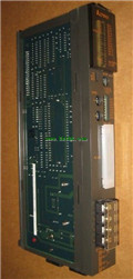
Name: MELSECNET/MINI-S3 Master Module
Brand: MITSUBISHI
Sort: User's Manual
File language: English
Download link: MITSUBISHI AJ71PT32-S3 User's Manual
Special multi axis positioning controller for NSD servo system.
Optical data communication line.
Program capacity: Max 60K step.
Input / output points: 1920 points.
When the switch is off, the diode does not emit light, and the transistor is not on the way. Internal circuit input signal.
It is through the input interface circuit to the external switch signal into PLC internal can accept the digital signal AJ71PT32-S3 Manual AJ71PT32-S3 User's Manual AJ71PT32-S3
Photoelectric three levels: in the light of the light signal conduction, the degree of light signal and the intensity of the light signal.
The output signal has a linear relationship with the input signal in the linear operating region of the photoelectric coupler.
User program storage capacity: it is a measure of how much the user application can store the number of indicators AJ71PT32-S3 Manual AJ71PT32-S3 User's Manual.
Usually in words or K words as units. 16 bit binary number is a word,
Every 1024 words are 1K words. PLC to store instructions and data in words.
General logical operation instructions each account for 1 words. Timer / counter,
Shift instruction accounted for 2 words. Data operation instructions for 2~4 AJ71PT32-S3 Manual AJ71PT32-S3 User's Manual.
The length of time required to execute the instruction, the length of the user''s program, the type of instruction, and the speed of the CPU execution are very significant,
Generally, a scanning process, the fault diagnosis time,
Communication time, input sampling and output refresh time is less,
The execution time is accounted for the vast majority of.
The photoelectric coupler is composed of two luminous two extreme tubes and a photoelectric transistor.
Light emitting diode two: the input of a photo coupler and the change of electrical signal,
The light signal is generated by the light emitting diode, which is the same as the input signal.
The working process of the input interface circuit: when the switch is closed, the diode light,
The transistor is then guided to the internal circuit and input signal under the irradiation of the light. 2 slots.
Can be installed in the power supply unit for A series units installed QnA/.
Cannot extend.
Relay output interface circuit of PLC
Working process: when the internal circuit output digital signal 1,
There is a current flowing through, the relay coil has a current, and then the normally open contact is closed,
Provide load current and voltage.
When the internal circuit outputs a digital signal 0, there is no current flowing through it,
The relay coil does not have a current, and the normally open contact is broken off,
A current or voltage that is disconnected from the load.
It is through the output interface circuit to the internal digital circuit into a signal to make the load action or not action.
I/O points is an important indicator of PLC.
Reasonable selection of I/O points can not only satisfy the control requirements of the system,
And the total investment of the system is the lowest.
The input and output points and types of PLC should be determined according to the analog quantity aand switch quantity of the controlled object,
Generally an input / output element to take up an input / output point AJ71PT32-S3 Manual AJ71PT32-S3 User's Manual.
Taking into account the future adjustment and expansion,
In general should be estimaated on the total number of points plus the amount of spare 20%~30% AJ71PT32-S3 Manual AJ71PT32-S3 User's Manual.
The following describes the centralized control system I/O points of the estimate.
Related products
MITSUBISHI
Master control module
A1SJ71PT32-S3
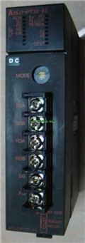
Cale type: cale or twisted pair.
A1SJ7

MITSUBISHI
MELSECNET/MINI-S3 module
AJ71PT32-S3
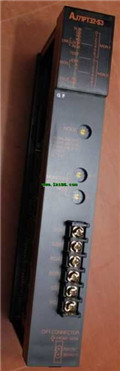
Fier optic cale / twisted pair cale.
MITSUBISHI
SUMINET module
AJ71P41
SUMINET-3200 network.
MITSUBISHI PLC det