 LK Automation Limited
Download Sort:
MITSUBISHI
MITSUBISHI A1SJ71T32-S3 datasheet PDF catalog A1SJ71T32-S3 PDF datasheet
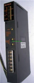
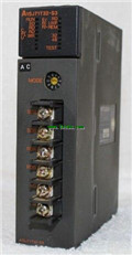
Product model: A1SJ71T32-S3
Name: Master control module
Brand: MITSUBISHI
Sort: PDF datasheet
File language: English
Download link: MITSUBISHI A1SJ71T32-S3 PDF datasheet
D-STN color / monochrome LCD man-machine interface to replace the backlight.
Applicable model: A970GOT-SB_/LB_. DC input points: 16 points.
Input voltage and current: 5mA, DC24V.
Response time: 10ms.
16 point /1 a public side.
Positive / negative sharing.
Output points: 16 points.
Output voltage and current: DC24V, 0 A1SJ71T32-S3 datasheet PDF catalog A1SJ71T32-S3 PDF datasheet. 1A/1 point, 1.6A/1 common end A1SJ71T32-S3
Response time: 2ms.
16 point /1 a public side.
Output form: transistor output, leakage type.
40 pin connector.
Number of stations: 4 stops.
According to the control requirements of the system, using the appropriate design method to design MITSUBISHI PLC program.
Procedures to meet the requirements of system control as the main line,
Write one by one to achieve the control function or the sub task of the program,
Gradually improve the functions specified by the system A1SJ71T32-S3 datasheet PDF catalog A1SJ71T32-S3 PDF datasheet.
MITSUBISHI PLC detection, fault diagnosis and display and other procedures.
These procedures are relatively independent, generally in the basic completion of the program design and then add.
Hardware simulation method is to use a number of hardware equipment to simulate the generation of the signal,
The signals are connected to the input end of the PLC system in a hard wired way, and the timeliness is strong A1SJ71T32-S3 datasheet PDF catalog A1SJ71T32-S3 PDF datasheet.
Software simulation method is in the MITSUBISHI PLC in the preparation of a set of simulation program,
The simulation provides the field signal, which is simple and easy to operate, but it is not easy to guarantee the timeliness.
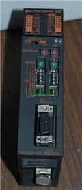
Simulation of the process of debugging, debugging method can be used to segment, and the monitoring function of programmer. NSD servo system.
A73CPU (P21/R21) -S3 dedicated.
Relay output interface circuit of PLC
Working process: when the internal circuit output digital signal 1,
There is a current flowing through, the relay coil has a current, and then the normally open contact is closed,
Provide load current and voltage.
When the internal circuit outputs a digital signal 0, there is no current flowing through it,
The relay coil does not have a current, and the normally open contact is broken off,
A current or voltage that is disconnected from the load.
It is through the output interface circuit to the internal digital circuit into a signal to make the load action or not action.
When the programmer input programinto the user program memory,
Then CPU according to the function of the system (the system program memory to explain the compiler),
Translate the user program into PLC internally recognized by the user to compile the program.
I/O points is an important indicator of PLC.
Reasonable selection of I/O points can not only satisfy the control requirements of the system,
And the total investment of the system is the lowest.
The input and output points and types of PLC should be determined according to the analog quantity and switch quanttity of the controlled object,
Generally an input / output element to take up an input / output point A1SJ71T32-S3 datasheet PDF catalog A1SJ71T32-S3 PDF datasheet.
Taking into account the future adjustment and expansion,
In general should be estimaated on the total number of points plus the amount of spare 20%~30% A1SJ71T32-S3 datasheet PDF catalog A1SJ71T32-S3 PDF datasheet.
The following describes the centralized control system I/O points of the estimate.
Applicable model: A970GOT-SB_/LB_. DC input points: 16 points.
Input voltage and current: 5mA, DC24V.
Response time: 10ms.
16 point /1 a public side.
Positive / negative sharing.
Output points: 16 points.
Output voltage and current: DC24V, 0 A1SJ71T32-S3 datasheet PDF catalog A1SJ71T32-S3 PDF datasheet. 1A/1 point, 1.6A/1 common end A1SJ71T32-S3
Response time: 2ms.
16 point /1 a public side.
Output form: transistor output, leakage type.
40 pin connector.
Number of stations: 4 stops.
According to the control requirements of the system, using the appropriate design method to design MITSUBISHI PLC program.
Procedures to meet the requirements of system control as the main line,
Write one by one to achieve the control function or the sub task of the program,
Gradually improve the functions specified by the system A1SJ71T32-S3 datasheet PDF catalog A1SJ71T32-S3 PDF datasheet.
MITSUBISHI PLC detection, fault diagnosis and display and other procedures.
These procedures are relatively independent, generally in the basic completion of the program design and then add.
Hardware simulation method is to use a number of hardware equipment to simulate the generation of the signal,
The signals are connected to the input end of the PLC system in a hard wired way, and the timeliness is strong A1SJ71T32-S3 datasheet PDF catalog A1SJ71T32-S3 PDF datasheet.
Software simulation method is in the MITSUBISHI PLC in the preparation of a set of simulation program,
The simulation provides the field signal, which is simple and easy to operate, but it is not easy to guarantee the timeliness.
Simulation of the process of debugging, debugging method can be used to segment, and the monitoring function of programmer. NSD servo system.
A73CPU (P21/R21) -S3 dedicated.
Relay output interface circuit of PLC
Working process: when the internal circuit output digital signal 1,
There is a current flowing through, the relay coil has a current, and then the normally open contact is closed,
Provide load current and voltage.
When the internal circuit outputs a digital signal 0, there is no current flowing through it,
The relay coil does not have a current, and the normally open contact is broken off,
A current or voltage that is disconnected from the load.
It is through the output interface circuit to the internal digital circuit into a signal to make the load action or not action.
When the programmer input programinto the user program memory,
Then CPU according to the function of the system (the system program memory to explain the compiler),
Translate the user program into PLC internally recognized by the user to compile the program.
I/O points is an important indicator of PLC.
Reasonable selection of I/O points can not only satisfy the control requirements of the system,
And the total investment of the system is the lowest.
The input and output points and types of PLC should be determined according to the analog quantity and switch quanttity of the controlled object,
Generally an input / output element to take up an input / output point A1SJ71T32-S3 datasheet PDF catalog A1SJ71T32-S3 PDF datasheet.
Taking into account the future adjustment and expansion,
In general should be estimaated on the total number of points plus the amount of spare 20%~30% A1SJ71T32-S3 datasheet PDF catalog A1SJ71T32-S3 PDF datasheet.
The following describes the centralized control system I/O points of the estimate.
Related products
MITSUBISHI
MELSECNET/MINI-S3 module
AJ71T32-S3
Twisted pair cale.
Single us.
Control
MITSUBISHI
Serial communication module
A1SJ71QC24N-R2
RS-232 2 channel.
Transfer speed: 2 chan
MITSUBISHI
Master control module
A1SJ71T32-S3
Cale type: twisted pair.
A1SJ71PT32-S3