 LK Automation Limited
Download Sort:
MITSUBISHI
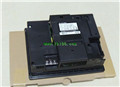
MITSUBISHI A985GOT-TBA Hardware Manual A985GOT-TBA User's Manual
Product model: A985GOT-TBA
Name: Graphic Operation Terminal
Brand: MITSUBISHI
Sort: Hardware User's Manual
File language: English
Download link: MITSUBISHI A985GOT-TBA User's Manual
MITSUBISHI PLC hardware implementation
Hardware implementation is mainly for the control cabinet and other hardware design and field construction.
Design control cabinet and the operating table and other parts of the electrical wiring diagram and wiring diagram.
Electrical interconnection diagram of each part of the design system A985GOT-TBA Hardware Manual A985GOT-TBA User's Manual.
According to the construction drawings of the site wiring, and carry out a detailed inspection A985GOT-TBA
Because the program design and hardware implementation can be carried out at the same time,
So the design cycle of the MITSUBISHI PLC control system can be greatly reduced. RS-232 2 channel.
Transfer speed: 2 channels.
A total of 115.2kbps.
Input status and input information input from the input interface,
CPU will be stored in the working data memory or in the input image register A985GOT-TBA Hardware Manual A985GOT-TBA User's Manual.
And then combine the data and the program with CPU.
The result is stored in the output image register or the working data memory,
And then output to the output interface, control the external drive.
Semiconductor circuit with memory function.
System program memory and user memory.
System program memory for storing system program,
Including management procedures, monitoring procedures, as well as the user program to do the compiler to compile the process of interpretation A985GOT-TBA Hardware Manual A985GOT-TBA User's Manual.
Read only memory. Manufacturers use, content can not be changed, power does not disappear. Input and output points: 480 points.
Program capacity: 7K step.
Basic command processing speed: 4.4 ~ 5.6us.
Power supply: input DC5V output 2A DC24V/.
Modular: PLC is the basic components of a separate module.
Medium and large PLC used this way. Easy maintenance.
Relay output interface circuit of PLC
Working process: when the internal circuit output digital signal 1,
There is a current flowing through, the relay coil has a current, and then the normally open contact is closed,
Provide load current and voltage.
When the internal circuit outputs a digital signal 0, there is no current flowing through it,
The relay coil does not have a current, and the normally open contact is broken off,
A current or voltage that is disconnected from the load.
It is through the output interface circuit to the internal digital circuit into a signal to make the load action or not action.
User program storage capacity: it is a measure of how much the user applicatiion can store the number of indicators A985GOT-TBA Hardware Manual A985GOT-TBA User's Manual.
Usually in words or K words as units. 16 bit binary number is a word,
Every 1024 words are 1K words. PLC to store instructions and data in words.
General llogical operation instructions each account for 1 words A985GOT-TBA Hardware Manual A985GOT-TBA User's Manual. Timer / counter,
Shift instruction accounted for 2 words. Data operation instructions for 2~4.
Related products
MITSUBISHI
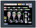
12 inch man machine interface
A985GOT-TBD
Series Name: A985GOT.
Size: 12 inches.
R
MITSUBISHI
12 inch man machine interface
A985GOT-TBA
Series Name: A985GOT.
Size: 12 inches.
R
MITSUBISHI
12 inch man machine interface
A985GOT-TBA-EU
Series Name: A985GOT.
Size: 12 inches.
R