LK Automation Limited
Download Sort:
MITSUBISHI
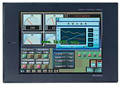
MITSUBISHI A975GOT-TBA-CH Hardware Manual A975GOT-TBA-CH User's Manual
Product model: A975GOT-TBA-CH
Name: touch screen
Brand: MITSUBISHI
Sort: Hardware User's Manual
File language: English
Download link: MITSUBISHI A975GOT-TBA-CH User's Manual
A pack of 10.
Applicable models:
AJ65VBTCE - -8 - type.
AJ65VBTCE - -16 - type. Cable length: 0.7 meters.
Extending cable to connect CPU main substrate and extended substrate,
According to the model can provide different cable length,
If you need to connect the AnN type expansion substrate is required,
Selection of A1SC05NB (A1SC07NB) cable A975GOT-TBA-CH Hardware Manual A975GOT-TBA-CH User's Manual A975GOT-TBA-CH SI-200/250 fiber optic cable.
Double loop.
MELSECNET (II) (Master / local station).
How to choose MITSUBISHI PLC.
MITSUBISHI PLC options include the choice of MITSUBISHI PLC models, capacity, I/O module, power, etc..
MITSUBISHI PLC distribution I/O points and design MITSUBISHI PLC peripheral hardware circuit
Draw the I/O point of the PLC and the input / output device connection diagram or the corresponding table,
This part also can be carried out in second steps A975GOT-TBA-CH Hardware Manual A975GOT-TBA-CH User's Manual.
Design PLC peripheral hardware circuit.
Draw the electrical wiring diagram of the other parts of the system,
Including the main circuit and the control circuit does not enter the PLC, etc..
The electrical schematic diagram of the system composed of I/O PLC connection diagram and PLC peripheral electrical circuit diagram A975GOT-TBA-CH Hardware Manual A975GOT-TBA-CH User's Manual.
So far the system''s hardware electrical circuit has been determined. AnS, QnAS bus connection, the reader to write program 1 channel connection.The use of A1STA32 can significantly reduce the wiring time I/O 32 type of connector assembly,
Neither welding, without thread stripping,
It only needs to cut a wire and insert the wire into the terminal hole of the A1STA32,
A1STA32 in the blade will cut wire insulation surface,
To make contact and hold a good conductor. Screw terminal table type.
Voltage / current input module.
Number of channels: 4 channels.
Number of stations: 1 stops.
Station type: remote equipment station.
MITSUBISHI PLC hardware implementation
Hardware implementation is mainly for the control cabinet and other hardware design and field construction.
Design control cabinet and the operating table and other parts of the electrical wiring diagram and wiring diagram.
Electrical interconnection diagram of each part of the design system.
According to the construction drawings of the site wiring, and carry out a detailed inspection.
Because the program design and hardware implementation can be carried out at the same time,
So the design cycle of the MITSUBISHI PLC control system can be greatly reduced.
MITSUBISHI PLC online debugging.
On-line debugging is the process that will through the simulation debugging to further carry on the on-line unification to adjust.
On-line debuggging process should be step by step,
From MITSUBISHI PLC only connected to the input device, and then connect the output device, and then connect to the actual load and so on and so on stepp by step A975GOT-TBA-CH Hardware Manual A975GOT-TBA-CH User's Manual A975GOT-TBA-CH Hardware Manual A975GOT-TBA-CH User's Manual.
If you do not meet the requirements, the hardware and procedures for adjustment.
Usually only need to modify the part of the program can be.
Related products
MITSUBISHI
10 inch man machine interface
A975GOT-TBA-B

Series Name: A975GOT.
Size: 10 inches.
R
MITSUBISHI
10 inch man machine interface
A975GOT-TBA-EU
Series Name: A975GOT.
Size: 10 inches.
R