LK Automation Limited
Download Sort:
MITSUBISHI
MITSUBISHI A80BDE-J61BT13 For SW3DNF-CCLINK Manual A80BDE-J61BT13 User's Manual
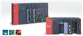
Product model: A80BDE-J61BT13
Name: CC-Link Interface Board
Brand: MITSUBISHI
Sort: For SW3DNF-CCLINK User's Manual
File language: English
Download link: MITSUBISHI A80BDE-J61BT13 User's Manual
10BASE5.
For Q mode.
Control layer /MELSECNET/10 (H) is the middle layer of the whole network system,
Control network which is convenient and high speed processing data transmission between PLC, CNC and other control equipment.
As MELSEC control network MELSECNET/10,
With its good real-time performance, simple network settings, no procedures of the network data sharing concept,
As well as the redundant circuit and so on, has obtained the very high market appraisal,
The number of devices to reach the highest in japan,
In the world is also one of the few A80BDE-J61BT13 For SW3DNF-CCLINK Manual A80BDE-J61BT13 User's Manual A80BDE-J61BT13
And MELSECNET/H not only inherited the excellent characteristics of MELSECNET/10,
Also makes the network real-time better, more data capacity,
Further adapt to the needs of the market A80BDE-J61BT13 For SW3DNF-CCLINK Manual A80BDE-J61BT13 User's Manual. I/O slots: 8 slots.
Outline dimension: 430*130.
CPU basic board can be plugged into 1 power modules,
1 CPU components and a maximum of 2, 3, 5, or 8 single slot size special function components and I/O components are respectively inserted and arranged.
Expansion ports are arranged on both sides of the base plate,
For connecting the expansion board for A80BDE-J61BT13 For SW3DNF-CCLINK Manual A80BDE-J61BT13 User's Manual.
Up to 3 extension substrates. Number of channels: RS422, 1 channel
.
Configuration of master / local station,
In addition to the other site network with different CC-Link in addition to the main station and the remote station configuration can also be the main station and the local station configuration.
A local PLC can communicate with the master station PLC and other remote workstations.
MITSUBISHI PLC online debugging.
On-line debugging is the process that will through the simulation debugging to further carry on the on-line unification to adjust.
On-line debugging process should be step by step,
From MITSUBISHI PLC only connected to the input device, and then connect the output device, and then connect to the actual load and so on and so on step by step.
If you do not meet the requirements, the hardware and procedures for adjustment.
Usually only need to modify the part of the program can be.
MITSUBISHI PLC hardware implementation
Hardware implementation is mainly for the control cabinet and other hardware design and field construction.
Design control cabinet and the operating table and other parts of the electrical wiring diagram and wiring diagram.
Electricaal interconnection diagram of each part of the design system A80BDE-J61BT13 For SW3DNF-CCLINK Manual A80BDE-J61BT13 User's Manual.
According to the construction drawings of the site wiring, and carry out a detailed inspection.
Because the program deesign and hardware implementation can be carried out at the same time,
So the design cycle of the MITSUBISHI PLC control system can be greatly reduced A80BDE-J61BT13 For SW3DNF-CCLINK Manual A80BDE-J61BT13 User's Manual.
Related products
MITSUBISHI
CC-Link connection unit
A8GT-J61BT13
CC-Link intelligent equipment station.
MITSUBISHI
CC-Link communication unit
GT15-J61BT13
Smart device site unit support for CC-L