LK Automation Limited
Download Sort:
MITSUBISHI
MITSUBISHI A80BDE-J61BT11 For SW3DNF-CCLINK Manual A80BDE-J61BT11 User's Manual
Product model: A80BDE-J61BT11
Name: CC-Link System Master/Local Interface Board
Brand: MITSUBISHI
Sort: For SW3DNF-CCLINK User's Manual
File language: English
Download link: MITSUBISHI A80BDE-J61BT11 User's Manual
Temperature sensor: PT100, 3 wire system.
The A1S62RD3 and A1S62RD4 temperature sensor input modules allow the platinum resistance temperature sensing element to be directly connected to the PLC,
This component converts a signal from a temperature measuring element to a numeric value that represents a temperature measurement value,
This temperature value can be used for the control process A80BDE-J61BT11 For SW3DNF-CCLINK Manual A80BDE-J61BT11 User's Manual A80BDE-J61BT11
The length of time required to execute the instruction, the length of the user''s program, the type of instruction, and the speed of the CPU execution are very significant,
Generally, a scanning process, the fault diagnosis time,
Communication time, input sampling and output refresh time is less,
The execution time is accounted for the vast majority of A80BDE-J61BT11 For SW3DNF-CCLINK Manual A80BDE-J61BT11 User's Manual.
The response time of PLC is the interval between the time of the change of the external output signal of the PLC and the time of the change of the external output signal which is controlled by it,
Lag time, this is the time constant of the input circuit,
The time constant of the output circuit, the arrangement of the user statement and the use of the instruction,
The cycle scan mode of PLC and the way of PLC to refresh the I/O and so on A80BDE-J61BT11 For SW3DNF-CCLINK Manual A80BDE-J61BT11 User's Manual.
This phenomenon is called the I/O delay time effect. Cable length: 10 meters.
For QnA/A/FX (FX1, FX2, FX2C) CPU and GOT connection between.
For connection between FA-CNV_CBL and GOT.
For connection between FX-2PIF and GOT.
For connection between FX-422AW0 and GOT.
For serial communication module AJ71QC24 (N) -R4 and GOT connection between.
For connection between AJ65BT-G4-S3 and GOT. SI/QSI/H-PCF/ wide range H-PCF fiber optic cable.
Double loop.
Remote I/O network (remote control station).
How to choose MITSUBISHI PLC.
MITSUBISHI PLC options include the choice of MITSUBISHI PLC models, capacity, I/O module, power, etc..
MITSUBISHI PLC distribution I/O points and design MITSUBISHI PLC peripheral hardware circuit
Draw the I/O point of the PLC and the input / output device connection diagram or the corresponding table,
This part also can be carried out in second steps.
Design PLC peripheral hardware circuit.
Draw the electrical wirring diagram of the other parts of the system,
Including the main circuit and the control circuit does not enter the PLC, etc A80BDE-J61BT11 For SW3DNF-CCLINK Manual A80BDE-J61BT11 User's Manual. .
The electrical schematic diagram of the system compoosed of I/O PLC connection diagram and PLC peripheral electrical circuit diagram A80BDE-J61BT11 For SW3DNF-CCLINK Manual A80BDE-J61BT11 User's Manual.
So far the system''s hardware electrical circuit has been determined.
Related products
MITSUBISHI
CC-Link module
AJ61BT11
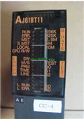
Master / local station.
AnCPU use.
Accor
MITSUBISHI
CC-Link module
A1SJ61BT11
Three remote components can e connected