 LK Automation Limited
Download Sort:
MITSUBISHI
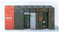
MITSUBISHI A3NCPUP21-S3 Dedicated Instructions Manual A3NCPUP21-S3 Programming Manual
Product model: A3NCPUP21-S3
Name: PLC
Brand: MITSUBISHI
Sort: Dedicated Instructions Programming Manual
File language: English
Download link: MITSUBISHI A3NCPUP21-S3 Programming Manual
Adapter for mounting rails. Unit connection CPU unit.Special multi axis positioning controller for NSD servo system.
Program capacity: Max 60K step.
Input / output points: 1920 points.
Control AC motor required I/O points with PLC control AC motor,
Signal and feedback signal is used as the input signal of PLC,
The control of AC motor is accomplished by using the output signal of PLC to drive the contactor A3NCPUP21-S3 Dedicated Instructions Manual A3NCPUP21-S3 Programming Manual A3NCPUP21-S3
For example, the AC motor is controlled by a Y- delta starting with PLC,
Generally need to occupy 4 of the PLC input and 3 output points,
PLC control of a one-way operation of the cage type motor,
4 input points and 1 output points are occupied, and a reversible motor is controlled,
5 input points and 2 output points are needed to control a unidirectional operation of variable pole speed control motor,
5 input points and 2 output points are required to control a unidirectional operation of the rotor AC motor,
3 input points and 4 output points are needed to control a reversible running winding rotor AC motor,
Requires 4 input points and 5 output points A3NCPUP21-S3 Dedicated Instructions Manual A3NCPUP21-S3 Programming Manual. 32: terminal line adapter 0 A3NCPUP21-S3 Dedicated Instructions Manual A3NCPUP21-S3 Programming Manual. 75mm2 (AGW18).Twisted pair cable.
Single bus.
MELSECNET/B (remote I/O station).
According to the control requirements of the system, using the appropriate design method to design MITSUBISHI PLC program.
Procedures to meet the requirements of system control as the main line,
Write one by one to achieve the control function or the sub task of the program,
Gradually improve the functions specified by the system.
MITSUBISHI PLC initialization procedure. After MITSUBISHI PLC on power, the general need to do some of the initial operation,
In order to start making necessary preparations, to avoid the wrong operation of the system.
The main contents of the initialization program are: to some data area, counter and so on,
Data needed to restore some of the data area,
Set or reset some relays,
For some initial state display, etc.. Input points: 16 points.
Input voltage and current: 240V ~ 10mA AC100.
Input response time: 35ms.
16 point /1 a public side.
Output points: 12 points.
Output voltage: AC100 ~ 240V.
OFF leakage current: 3mA.
Output response time: 0.5Hz+1ms.
Output type: bidirectional thyristor output.
8 point /1 a public end, 4 points / a public end.
36 point terminal station.
With short circuit protection.
With the surge absorber.
Control solenoid valve required I/O points by the action principle of the solenoid valve can be known,
A single coil solenoid valve with PLC control to 2 input and 1 output,
A double coil solenoid valve requires 3 inputs and 2 outputs,
A button needs an input; a light sensitive switch needs 4 or 2 inputs,
A signal lamp needs 1 output, band switch,
Several bands are required for several inputs,
In general, a variety of position switches are required to take up 2 input points.
MITSUBISHI PLC is the main product in the production of MITSUBISHI motor in Dalian.
It uses a kind of programmable memory for its internal storage procedures,
Execute logic operation, sequence control, timing, counting and arithmetic operations, user oriented instruction,
And through digital or analog input / output control of various types of machinery or production process.
The number of I/O thyristor DC motor control required tube DC motor speed control system is the main form of DC speed regulation,
The thyristor rectifier unit is used to supply power to the DC motor.
PLC control of the DC drive system, the input of the PLC in addition to the main signal outside the signal,
We need to consider the switching signal, the fault signal transmission device, brake signal and fan fault signal.
The output of thee PLC mainly consider the speed command signal positive 1~3 level, 1~3 level, allowing reverse switching signal and brake open signal etc A3NCPUP21-S3 Dedicated Instructions Manual A3NCPUP21-S3 Programming Manual. .
In general, a reversible DC drivee system controlled by PLC is approximately 12 input points and 8 output points,
An irreversible DC drive system requires 9 inputs and 6 output points A3NCPUP21-S3 Dedicated Instructions Manual A3NCPUP21-S3 Programming Manual.
Related products
MITSUBISHI
Melsecnet interface module
A1SJ71AP21-S3
PLC station distance: 2Km.
Cale type: G
MITSUBISHI
CPU unit
A3NCPU
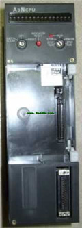
Input and output points: 2048 points.
In
MITSUBISHI
Moving CPU unit
A73CPUP21-S3

Special multi axis positioning controlle
MITSUBISHI
CPU unit
A2ACPUP21-S3
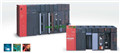
Input and output points: 512 points.
Inp