 LK Automation Limited
Download Sort:
MITSUBISHI
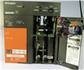
MITSUBISHI A2UCPU-S1 Manual A2UCPU-S1 User's Manual
Product model: A2UCPU-S1
Name: Programmable Controller
Brand: MITSUBISHI
Sort: User's Manual
File language: English
Download link: MITSUBISHI A2UCPU-S1 User's Manual
Input voltage range: DC24V.
Output voltage: DC5V.
Output current: 2.5A.
I/O points is an important indicator of PLC.
Reasonable selection of I/O points can not only satisfy the control requirements of the system,
And the total investment of the system is the lowest.
The input and output points and types of PLC should be determined according to the analog quantity and switch quantity of the controlled object,
Generally an input / output element to take up an input / output point A2UCPU-S1 Manual A2UCPU-S1 User's Manual A2UCPU-S1
Taking into account the future adjustment and expansion,
In general should be estimated on the total number of points plus the amount of spare 20%~30%.
The following describes the centralized control system I/O points of the estimate A2UCPU-S1 Manual A2UCPU-S1 User's Manual.
Relay output interface circuit of PLC
Working process: when the internal circuit output digital signal 1,
There is a current flowing through, the relay coil has a current, and then the normally open contact is closed,
Provide load current and voltage.
When the internal circuit outputs a digital signal 0, there is no current flowing through it,
The relay coil does not have a current, and the normally open contact is broken off,
A current or voltage that is disconnected from the load A2UCPU-S1 Manual A2UCPU-S1 User's Manual.
It is through the output interface circuit to the internal digital circuit into a signal to make the load action or not action. 2 channels.
3 wire platinum measuring antibodies (Pt100, JPt100).
Transform speed: 40ms/1 channel.
20 point terminal station.
The popularization and application of PLC programming has been developed rapidly in our country,
It has been widely used in all kinds of mechanical equipment and production process of electrical control devices,
All walks of life have emerged a large number of application of PLC transformation of the results of the equipment.
Understand the working principle of PLC, have the ability to design, debug and maintain the PLC control system,
Has become the basic requirements of modern industry for electrical technicians and engineering students.
PLC user program is designed according to the control system of the process control requirements,
PLC programming language through the preparation of specifications, in accordance with the actual needs of the use of the function to design.
As long as the user can master some kind of standard programming language,
To be able to use PLC in the control system,
To achieve a variety of automatic control functions.
The instruction list programming language is a programming language similar to assembly language mnemonic,
As well as assembly language by the operation code and the number of operations.
In the case of the computer for the PLC handheld programmer compile user program.
At the same time, the programming language of the instruction list corresponds to the ladder diagram programming language,
In PLC programming software can be converted to each other. Figure 3 is the instruction sheet corresponding to the ladder diagram of figure 2PLC.
The characteristics of instruction table programming language is used to represent mnemonic operation function,
Easy to remember, easy to grasp;
In the handheld programmer on the keyboard using the mnemonic representation, easy to operate, can be programmed in computer;
There is a one-to-one correspondence between the ladder diagram and the ladder diagram. Its characteristics are basically consistent with the ladder diagram language.
Functional block diagram language is a kind of PLC programming language, which is similar to digital logic circuit.
The function module is used to represent the function of the module,
Different function modules have different functions.
Functional module figure programming language features: functional block diagram programming language is characterized by a functional module for the unit,
Analysis and understanding of the control scheme is simple and easy: funnction module is to use graphical form of expression,
Intuitive, for a digital logic circuit based on the design of the staff is very easy to master the programming;
Control system with complex scale and coomplex control logic,
Because the function module diagram can clearly express the function relation, the programming debugging time is greatly reduced A2UCPU-S1 Manual A2UCPU-S1 User's Manual A2UCPU-S1 Manual A2UCPU-S1 User's Manual.
Related products
MITSUBISHI
CPU unit
A2USHCPU-S1
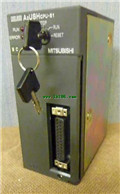
I/O points: 1024.
Processing speed: 0.09
MITSUBISHI
CPU unit
Q2ASCPU-S1
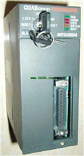
Input and output points: 1024 points.
In
MITSUBISHI
Motion CPU module
Q173DCPU-S1

Upgraded version.
Control axis: maximum