LK Automation Limited
Download Sort:
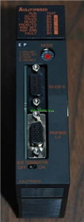
MITSUBISHI
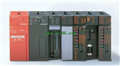
MITSUBISHI A1SJ72QBR15 Hardware Manual A1SJ72QBR15 User's Manual
Product model: A1SJ72QBR15
Name: MELSECNET/10 Remote I/O Module
Brand: MITSUBISHI
Sort: Hardware User's Manual
File language: English
Download link: MITSUBISHI A1SJ72QBR15 User's Manual
Output points: 24 points.
Voltage: DC24V/AC240V, 2A/1 point, 8A/1 public end.
Output type: relay output.
Response time: 12ms.
8 point /1 a public side.
38 point terminal station.
CE certification.
The number of I/O thyristor DC motor control required tube DC motor speed control system is the main form of DC speed regulation,
The thyristor rectifier unit is used to supply power to the DC motor A1SJ72QBR15 Hardware Manual A1SJ72QBR15 User's Manual A1SJ72QBR15
PLC control of the DC drive system, the input of the PLC in addition to the main signal outside the signal,
We need to consider the switching signal, the fault signal transmission device, brake signal and fan fault signal.
The output of the PLC mainly consider the speed command signal positive 1~3 level, 1~3 level, allowing reverse switching signal and brake open signal etc A1SJ72QBR15 Hardware Manual A1SJ72QBR15 User's Manual. .
In general, a reversible DC drive system controlled by PLC is approximately 12 input points and 8 output points,
An irreversible DC drive system requires 9 inputs and 6 output points.
MITSUBISHI PLC is the main product in the production of MITSUBISHI motor in Dalian.
It uses a kind of programmable memory for its internal storage procedures,
Execute logic operation, sequence control, timing, counting and arithmetic operations, user oriented instruction,
And through digital or analog input / output control of various types of machinery or production process A1SJ72QBR15 Hardware Manual A1SJ72QBR15 User's Manual.
Control solenoid valve required I/O points by the action principle of the solenoid valve can be known,
A single coil solenoid valve with PLC control to 2 input and 1 output,
A double coil solenoid valve requires 3 inputs and 2 outputs,
A button needs an input; a light sensitive switch needs 4 or 2 inputs,
A signal lamp needs 1 output, band switch,
Several bands are required for several inputs,
In general, a variety of position switches are required to take up 2 input points. AnS, QnAS bus connection, the reader to write program 2 channel connection.
Input status and input information input from the input interface,
CPU will be stored in the working data memory or in the input image register.
And then combine the data and the program with CPU.
The result is stored in the output image register or the working data memory,
And then output to the output interface, control the external drive.
The response time of PLC is the interval between the time of the change of the external output signal of the PLC and the time of the change of the exteernal output signal which is controlled by it,
Lag time, this is the time constant of the input circuit,
The time constant of the output circuit, the arrangement of the user statement and the usse of the instruction,
The cycle scan mode of PLC and the way of PLC to refresh the I/O and so on A1SJ72QBR15 Hardware Manual A1SJ72QBR15 User's Manual A1SJ72QBR15 Hardware Manual A1SJ72QBR15 User's Manual.
This phenomenon is called the I/O delay time effect.
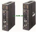
Related products
MITSUBISHI
Profibus interface module
A1SJ71PB96F
Availale network: Profius-FMS.
Functio
MITSUBISHI
Ethernet module
A1SJ71E71N3-T
10BASE-T.
The structured text programmin
MITSUBISHI
Profibus interface module
A1SJ71PB92D
Availale network: Profius-DP.
Function