LK Automation Limited
Download Sort:
MITSUBISHI
MITSUBISHI A1SJ71E71-B2 Hardware Manual A1SJ71E71-B2 User's Manual
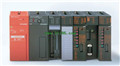
Product model: A1SJ71E71-B2
Name: Ethernet Interface Module
Brand: MITSUBISHI
Sort: Hardware User's Manual
File language: English
Download link: MITSUBISHI A1SJ71E71-B2 User's Manual
Input voltage range: DC110V.
Output voltage: DC5V.
Output current: 8A.
I/O points is an important indicator of PLC.
Reasonable selection of I/O points can not only satisfy the control requirements of the system,
And the total investment of the system is the lowest.
The input and output points and types of PLC should be determined according to the analog quantity and switch quantity of the controlled object,
Generally an input / output element to take up an input / output point A1SJ71E71-B2 Hardware Manual A1SJ71E71-B2 User's Manual A1SJ71E71-B2
Taking into account the future adjustment and expansion,
In general should be estimated on the total number of points plus the amount of spare 20%~30%.
The following describes the centralized control system I/O points of the estimate A1SJ71E71-B2 Hardware Manual A1SJ71E71-B2 User's Manual. MELSECNET/MINI (-S3) data link system, A2C system transfer converter.
Twisted pair cable -SI optical fiber cable.
MITSUBISHI PLC protection and chain procedures.
Protection and chain is an indispensable part of the program, must be carefully considered.
It can avoid the control logic confusion caused by illegal operations.
MITSUBISHI PLC initialization procedure. After MITSUBISHI PLC on power, the general need to do some of the initial operation,
In order to start making necessary preparations, to avoid the wrong operation of the system A1SJ71E71-B2 Hardware Manual A1SJ71E71-B2 User's Manual.
The main contents of the initialization program are: to some data area, counter and so on,
Data needed to restore some of the data area,
Set or reset some relays,
For some initial state display, etc..
MITSUBISHI PLC program simulation debugging
The basic idea of program simulation debugging is,
In order to facilitate the form of simulation to generate the actual state of the scene,
Create the necessary environmental conditions for the operation of the program.
Depending on the way the field signals are generated,
The simulation debugging has two forms of hardware simulation and software simulation. Input and output points: 512 points.
Input / output data points: 512 points.
Program capacity: 14K.
Basic command processing speed (LD command) s:1.0.
Optical data communication line function (GI cable).
Each scanning process. Focus on the input signal sampling. Focus on the output signal to refresh.
Input refresh process. When the input port is closed,
Program in the implementation phase, the input end of a new state, the new state can not be read.
Only when the program is scanned, the new state is read.
A scan cycle is divided into the input sample, the program execution, the output refresh.
The contents of the component image register are changed with the change of the execution of the program.
The length of the scan cycle is determined by the three.
CPU the speed of executing instructions.
Time of instruction.
Instruction count.
Due to the adoption of centralized sampling.
Centralized output mode.
There exist input / output hysteresis phenomena, i.e., the input / output response delay.
User program storage capacity: it is a measure of how much the user applicationn can store the number of indicators A1SJ71E71-B2 Hardware Manual A1SJ71E71-B2 User's Manual.
Usually in words or K words as units. 16 bit binary number is a word,
Every 1024 words are 1K words. PLC to store instructions and data in words.
General llogical operation instructions each account for 1 words A1SJ71E71-B2 Hardware Manual A1SJ71E71-B2 User's Manual. Timer / counter,
Shift instruction accounted for 2 words. Data operation instructions for 2~4.
Related products
MITSUBISHI
Profibus interface module
A1SJ71PB96F
Availale network: Profius-FMS.
Functio
MITSUBISHI
Ethernet module
QJ71E71-B2
"10BASE2.
Ethernet interface module capa