 LK Automation Limited
Download Sort:
MITSUBISHI
MITSUBISHI A1SJ71AT21B Hardware Manual A1SJ71AT21B User's Manual
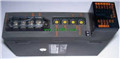
Product model: A1SJ71AT21B
Name: MELSECNET/B data link module
Brand: MITSUBISHI
Sort: Hardware User's Manual
File language: English
Download link: MITSUBISHI A1SJ71AT21B User's Manual
Peripheral equipment A/QnA series CPU unit connection cable.Number of channels: 2 channels.
Sensing methods and temperature range: R, K, J, T, S, B, E, N, U, L, PL, II,, Wre5-26,,, and.
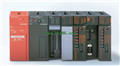
A1S64TC series component is a kind of temperature controller combined with ANS series CPU.
Components with temperature measurement input and built-in PID algorithm control output, can be used in a variety of temperature control occasions A1SJ71AT21B Hardware Manual A1SJ71AT21B User's Manual A1SJ71AT21B
Each component controls up to 4 loops at most.
Thermocouple input or PT100 3 wire temperature sensor input.
Control output switching signal for the output of the transistor.
BW is a signal with broken line detection function. Input type: DC input, negative public end.
Input points: 16 points A1SJ71AT21B Hardware Manual A1SJ71AT21B User's Manual.
Enter the response time: 1.5ms the following.
Rated input voltage / current: DC24V/7mA.
Output form: transistor output, source.
Output points: 16 points.
OFF leakage current: 0.1mA.
Output protection function: No.
Rated load voltage / current: DC24V/0.5A.
External connection: 1 line /1 line type.
According to the external connection mode and the external equipment input and output specifications,
Choose from a rich product lineup A1SJ71AT21B Hardware Manual A1SJ71AT21B User's Manual.
Finger protection through the upper part of the terminal,
The human body will not be exposed to live parts,
Therefore, the terminal station type remote I/O module can be directly mounted to the machine tool. AnS, QnAS bus connection, the reader to write program 1 channel connection.
Input status and input information input from the input interface,
CPU will be stored in the working data memory or in the input image register.
And then combine the data and the program with CPU.
The result is stored in the output image register or the working data memory,
And then output to the output interface, control the external drive.
The response time of PLC is the interval between the time of the change of the external output signal of the PLC and the time of the change of the exteernal output signal which is controlled by it,
Lag time, this is the time constant of the input circuit,
The time constant of the output circuit, the arrangement of the user statement and the usse of the instruction,
The cycle scan mode of PLC and the way of PLC to refresh the I/O and so on A1SJ71AT21B Hardware Manual A1SJ71AT21B User's Manual A1SJ71AT21B Hardware Manual A1SJ71AT21B User's Manual.
This phenomenon is called the I/O delay time effect.
Sensing methods and temperature range: R, K, J, T, S, B, E, N, U, L, PL, II,, Wre5-26,,, and.
A1S64TC series component is a kind of temperature controller combined with ANS series CPU.
Components with temperature measurement input and built-in PID algorithm control output, can be used in a variety of temperature control occasions A1SJ71AT21B Hardware Manual A1SJ71AT21B User's Manual A1SJ71AT21B
Each component controls up to 4 loops at most.
Thermocouple input or PT100 3 wire temperature sensor input.
Control output switching signal for the output of the transistor.
BW is a signal with broken line detection function. Input type: DC input, negative public end.
Input points: 16 points A1SJ71AT21B Hardware Manual A1SJ71AT21B User's Manual.
Enter the response time: 1.5ms the following.
Rated input voltage / current: DC24V/7mA.
Output form: transistor output, source.
Output points: 16 points.
OFF leakage current: 0.1mA.
Output protection function: No.
Rated load voltage / current: DC24V/0.5A.
External connection: 1 line /1 line type.
According to the external connection mode and the external equipment input and output specifications,
Choose from a rich product lineup A1SJ71AT21B Hardware Manual A1SJ71AT21B User's Manual.
Finger protection through the upper part of the terminal,
The human body will not be exposed to live parts,
Therefore, the terminal station type remote I/O module can be directly mounted to the machine tool. AnS, QnAS bus connection, the reader to write program 1 channel connection.
Input status and input information input from the input interface,
CPU will be stored in the working data memory or in the input image register.
And then combine the data and the program with CPU.
The result is stored in the output image register or the working data memory,
And then output to the output interface, control the external drive.
The response time of PLC is the interval between the time of the change of the external output signal of the PLC and the time of the change of the exteernal output signal which is controlled by it,
Lag time, this is the time constant of the input circuit,
The time constant of the output circuit, the arrangement of the user statement and the usse of the instruction,
The cycle scan mode of PLC and the way of PLC to refresh the I/O and so on A1SJ71AT21B Hardware Manual A1SJ71AT21B User's Manual A1SJ71AT21B Hardware Manual A1SJ71AT21B User's Manual.
This phenomenon is called the I/O delay time effect.
Related products
MITSUBISHI
Melsecnet interface module
A1SJ71AT21B
Cale type: twisted pair cale.
The func
MITSUBISHI
Melsecnet interface module
A1SJ71AP21-S3

PLC station distance: 2Km.
Cale type: G
MITSUBISHI
Ethernet module
A1SJ71QE71N-B2
10BASE2.
Q mode.
MITSUBISHI PLC is the m
MITSUBISHI
Melsecnet interface module
A1SJ71AP21GE

PLC station distance: 2Km.
Cale type: G