 LK Automation Limited
Download Sort:
MITSUBISHI
MITSUBISHI A1SD75P2 Manual A1SD75P2 User's Manual
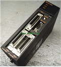
Product model: A1SD75P2
Name: Positioning Module
Brand: MITSUBISHI
Sort: User's Manual
File language: English
Download link: MITSUBISHI A1SD75P2 User's Manual
Memory card interface (AD59-MEF), parallel interface.
On-line debugging is the process that will through the simulation debugging to further carry on the on-line unification to adjust.
On-line debugging process should be step by step,
From MITSUBISHI PLC only connected to the input device, and then connect the output device, and then connect to the actual load and so on and so on step by step A1SD75P2 Manual A1SD75P2 User's Manual A1SD75P2
If you do not meet the requirements, the hardware and procedures for adjustment.
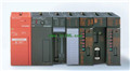
Usually only need to modify the part of the program can be. CPU:A2SHCPU PLC is the same.
PLC program capacity: 14k step.
I/O points: 512 points.
Processing speed (sequential order): 0.25 s/ step.
Control axis: up to 4.
Servo program capacity: 13K step A1SD75P2 Manual A1SD75P2 User's Manual.
Servo amplifier: SSCNET connected external servo amplifier.
PLC programming has a wide range of applications, powerful, easy to use, has become one of the main devices of modern industrial automation,
In all areas of industrial production has been widely used,
Applications in other areas (such as civil and home automation) have also been rapidly developed.
It uses programmable memory,
An instruction used to perform logical operations, sequence control, timing, counting and arithmetic operations in its internal storage,
And through digital, analog input and output,
Control of various types of machinery or production processes A1SD75P2 Manual A1SD75P2 User's Manual. Programmable controller and related equipment,
Should be easy to make the industrial control system to form a whole, easy to expand the principle design of its functions.
As can be seen from the above definition, PLC is a program to change the control function of the industrial control computer,
In addition to the completion of a wide variety of control functions, as well as with other computer communications networking features. 2 channels.
4 wire platinum measuring antibodies (Pt100, JPt100).
Transform speed: 40ms/1 channel.
20 point terminal station.
The popularization and application of PLC programming has been developed rapidly in our country,
It has been widely used in all kinds of mechanical equipment and production process of electrical control devices,
All walks of life have emerged a large number of application of PLC transformation of the results of the equipment.
Understand the working principle of PLC, have the ability to design, debug and maintain the PLC control system,
Has become the basic requirements of modern industry for electrical technicians and engineering students.
PLC user program is designed according to the control system of the process control requirements,
PLC programming language through the preparation of specifications, in accordance with the actual needs of the use of the function to design.
As long as the user can master some kind of standard programming language,
To be able to use PLC in the control system,
To achieve a variety of automatic control functions.
The instruction list programming language is a programming language similar to assembly language mnemonic,
As well as assembly language by the operation code and the number of operations.
In the case of the computer for the PLC handheld programmer compile user program.
At the same time, the programming language of the instruction list corresponds to the ladder diagram programming language,
In PLC programming software can be converted to each other. Figure 3 is the instruction sheet corresponding to the ladder diagram of figure 2PLC.
The characteristics of instruction table programming language is used to represent mnemonic operation function,
Easy to remember, easy to grasp;
In the handheld programmer on the keyboard using the mnemonic representation, easy to operate, can be programmed in computer;
There is a one-to-one correspondence between the ladder diagram and the ladder diagram. Its characteristics are basically consistent with the ladder diagram language.
Functional block diagram language is a kind of PLC programming language, which is similar to digital logic circuit.
The function module is used to represent the function of the module,
Different function modules have different functions.
Functional module figure programming language features: functional block diagram programming language is characterized by a functional module for the unit,
Analysis and understanding of the control scheme is simple and easy: function module is to use graphical form of expression,
Intuitive, for a digital logic circuit based on the design of the staff is very easy to master the programming;
Control system with complex scale and coomplex control logic,
Because the function module diagram can clearly express the function relation, the programming debugging time is greatly reduced A1SD75P2 Manual A1SD75P2 User's Manual A1SD75P2 Manual A1SD75P2 User's Manual.
On-line debugging is the process that will through the simulation debugging to further carry on the on-line unification to adjust.
On-line debugging process should be step by step,
From MITSUBISHI PLC only connected to the input device, and then connect the output device, and then connect to the actual load and so on and so on step by step A1SD75P2 Manual A1SD75P2 User's Manual A1SD75P2
If you do not meet the requirements, the hardware and procedures for adjustment.
Usually only need to modify the part of the program can be. CPU:A2SHCPU PLC is the same.
PLC program capacity: 14k step.
I/O points: 512 points.
Processing speed (sequential order): 0.25 s/ step.
Control axis: up to 4.
Servo program capacity: 13K step A1SD75P2 Manual A1SD75P2 User's Manual.
Servo amplifier: SSCNET connected external servo amplifier.
PLC programming has a wide range of applications, powerful, easy to use, has become one of the main devices of modern industrial automation,
In all areas of industrial production has been widely used,
Applications in other areas (such as civil and home automation) have also been rapidly developed.
It uses programmable memory,
An instruction used to perform logical operations, sequence control, timing, counting and arithmetic operations in its internal storage,
And through digital, analog input and output,
Control of various types of machinery or production processes A1SD75P2 Manual A1SD75P2 User's Manual. Programmable controller and related equipment,
Should be easy to make the industrial control system to form a whole, easy to expand the principle design of its functions.
As can be seen from the above definition, PLC is a program to change the control function of the industrial control computer,
In addition to the completion of a wide variety of control functions, as well as with other computer communications networking features. 2 channels.
4 wire platinum measuring antibodies (Pt100, JPt100).
Transform speed: 40ms/1 channel.
20 point terminal station.
The popularization and application of PLC programming has been developed rapidly in our country,
It has been widely used in all kinds of mechanical equipment and production process of electrical control devices,
All walks of life have emerged a large number of application of PLC transformation of the results of the equipment.
Understand the working principle of PLC, have the ability to design, debug and maintain the PLC control system,
Has become the basic requirements of modern industry for electrical technicians and engineering students.
PLC user program is designed according to the control system of the process control requirements,
PLC programming language through the preparation of specifications, in accordance with the actual needs of the use of the function to design.
As long as the user can master some kind of standard programming language,
To be able to use PLC in the control system,
To achieve a variety of automatic control functions.
The instruction list programming language is a programming language similar to assembly language mnemonic,
As well as assembly language by the operation code and the number of operations.
In the case of the computer for the PLC handheld programmer compile user program.
At the same time, the programming language of the instruction list corresponds to the ladder diagram programming language,
In PLC programming software can be converted to each other. Figure 3 is the instruction sheet corresponding to the ladder diagram of figure 2PLC.
The characteristics of instruction table programming language is used to represent mnemonic operation function,
Easy to remember, easy to grasp;
In the handheld programmer on the keyboard using the mnemonic representation, easy to operate, can be programmed in computer;
There is a one-to-one correspondence between the ladder diagram and the ladder diagram. Its characteristics are basically consistent with the ladder diagram language.
Functional block diagram language is a kind of PLC programming language, which is similar to digital logic circuit.
The function module is used to represent the function of the module,
Different function modules have different functions.
Functional module figure programming language features: functional block diagram programming language is characterized by a functional module for the unit,
Analysis and understanding of the control scheme is simple and easy: function module is to use graphical form of expression,
Intuitive, for a digital logic circuit based on the design of the staff is very easy to master the programming;
Control system with complex scale and coomplex control logic,
Because the function module diagram can clearly express the function relation, the programming debugging time is greatly reduced A1SD75P2 Manual A1SD75P2 User's Manual A1SD75P2 Manual A1SD75P2 User's Manual.
Related products
MITSUBISHI
Positioning control module
A1SD75M3
Axis of control: 3 axis linkage, 3 axis
MITSUBISHI
Reader module
A1SD32ID2

AnS, QnAS us connection, the reader to
MITSUBISHI
High speed counting module
A1SD62D-S1
2 channels.
200/10kpps.
Count input sign
MITSUBISHI
The PC card interface unit
A1SD59J-MIF

SRAM PC card.
Applicale models: A95_GOT