 LK Automation Limited
Download Sort:
MITSUBISHI
MITSUBISHI A1SD75M2 Manual A1SD75M2 User's Manual
Product model: A1SD75M2
Name: POsitioning Module
Brand: MITSUBISHI
Sort: User's Manual
File language: English
Download link: MITSUBISHI A1SD75M2 User's Manual
32 point connector for compression connector (40 pin connector.Input type: DC input, positive common end.
Input points: 8 points.
Enter the response time: 10ms the following.
Rated input voltage / current: DC24V/7mA.
Output form: transistor output, leakage type.
Output points: 8 points.
OFF leakage current: 0 A1SD75M2 Manual A1SD75M2 User's Manual. 1mA.
Output protection function: No.
Rated load voltage / current: DC12V/DC24V/0 A1SD75M25A.
External connection: 2 line /2 line type.
Type of input and output terminal.
Using 2 pieces of structure of the terminal units, maintenance can be maintained in the same line under the condition of the replacement module. JEMANET (OPCN-1) interface unit from the station.
The response time of PLC is the interval between the time of the change of the external output signal of the PLC and the time of the change of the external output signal which is controlled by it,
Lag time, this is the time constant of the input circuit,
The time constant of the output circuit, the arrangement of the user statement and the use of the instruction,
The cycle scan mode of PLC and the way of PLC to refresh the I/O and so on A1SD75M2 Manual A1SD75M2 User's Manual A1SD75M2 Manual A1SD75M2 User's Manual.
This phenomenon is called the I/O delay time effect.
Input status and input information input from the input interface,
CPU will be stored in the working data memory or in the input image register.
And then combine the data and the program with CPU.
The result is stored in the output image register or the working data memory,
And then output to the output interface, control the external drive. Enter 8 points: 24VDC.
4 wire type.
Response time: 1.5ms.
Output 8 points: 24VDC.
Transistor output.
Waterproof connector type.
MITSUBISHI PLC hardware implementation
Hardware implementation is mainly for the control cabinet and other hardware design and field construction.
Design control cabinet and the operating table and other parts of the electrical wiring diagram and wiring diagram.
Electrical interconnection diagram of each part of the design system.
According to the construction drawings of the site wiring, and carry out a detailed inspection.
Because the program design and hardware implementation can be carried out at the same time,
So the design cycle of the MITSUBISHI PLC control system can be greatly reduced.
MITSUBISHI PLC online debugging.
On-line debugging is the process that will through the simulation debugging to further carry on the on-line unification to addjust A1SD75M2 Manual A1SD75M2 User's Manual.
On-line debugging process should be step by step,
From MITSUBISHI PLC only connected to the input device, and then connect the output device, and then connect to the actual load and so on and so on stepp by step A1SD75M2 Manual A1SD75M2 User's Manual.
If you do not meet the requirements, the hardware and procedures for adjustment.
Usually only need to modify the part of the program can be.
Related products
MITSUBISHI
Positioning control module
A1SD75P3-S3
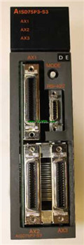
Axis of control: 3 axis linkage, 3 axis
MITSUBISHI
The PC card interface unit
A1SD59J-MIF

SRAM PC card.
Applicale models: A95_GOT
MITSUBISHI
High speed counting module
A1SD61
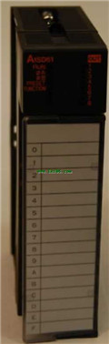
The A1SD61 high speed counting module ca
MITSUBISHI
Intelligent communication module
A1SD51S
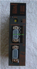
A1SD51S is an intelligent communication