Download Sort:
MITSUBISHI
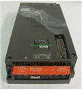
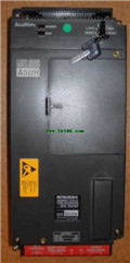
MITSUBISHI A0J2HCPU-DC24 Manual A0J2HCPU-DC24 Programming Manual
Product model: A0J2HCPU-DC24
Name: PLC
Brand: MITSUBISHI
Sort: Programming Manual
File language: English
Download link: MITSUBISHI A0J2HCPU-DC24 Programming Manual
Input points: 16 points.
Input voltage and current: 120V ~ 6mA AC100.
Input response time: 30ms.
16 point /1 a public side.
Output points: 16 points.
Output voltage: DC24V/AC240V, 2A/1 point, 4A/ common end.
Output response time: 12ms.
Output type: relay.
8 point /1 a public side.
50 point terminal station A0J2HCPU-DC24 Manual A0J2HCPU-DC24 Programming Manual.
The number of I/O thyristor DC motor control required tube DC motor speed control system is the main form of DC speed regulation,
The thyristor rectifier unit is used to supply power to the DC motor A0J2HCPU-DC24
PLC control of the DC drive system, the input of the PLC in addition to the main signal outside the signal,
We need to consider the switching signal, the fault signal transmission device, brake signal and fan fault signal A0J2HCPU-DC24 Manual A0J2HCPU-DC24 Programming Manual.
The output of the PLC mainly consider the speed command signal positive 1~3 level, 1~3 level, allowing reverse switching signal and brake open signal etc..
In general, a reversible DC drive system controlled by PLC is approximately 12 input points and 8 output points,
An irreversible DC drive system requires 9 inputs and 6 output points.
MITSUBISHI PLC is the main product in the production of MITSUBISHI motor in Dalian A0J2HCPU-DC24 Manual A0J2HCPU-DC24 Programming Manual.
It uses a kind of programmable memory for its internal storage procedures,
Execute logic operation, sequence control, timing, counting and arithmetic operations, user oriented instruction,
And through digital or analog input / output control of various types of machinery or production process.
Control solenoid valve required I/O points by the action principle of the solenoid valve can be known,
A single coil solenoid valve with PLC control to 2 input and 1 output,
A double coil solenoid valve requires 3 inputs and 2 outputs,
A button needs an input; a light sensitive switch needs 4 or 2 inputs,
A signal lamp needs 1 output, band switch,
Several bands are required for several inputs,
In general, a variety of position switches are required to take up 2 input points.
Type of input: DC source.
Input points: 16 points.
Input voltage: DC24.
Input current: 7mA.
Connection mode: terminal row.
Common common point: 16.
Sequential function flow chart language is designed to satisfy the sequential logic control.
The process of sequential process action is divided into steps and transformation conditions,
According to the transfer condition, the control system is distributed in the function flow sequence,
Step by step according to the sequence of actions.
Each step represents a control function, represented by the box.
In the box, the ladder logic is used to complete the task of the corresponding control function.
This programming language makes the program structure clear and easy to read and maintain,
Greatly reduce the programming workload, shorten the programming and debugging time.
Used in the system of the size of the school, procedures for more complex occasions.
Sequence function flow chart programming language features: to function as the main line, in accordance with the functional flow of the order of distribution, clear, eeasy to understand the user program,
Avoid the defect of ladder diagram or other languages,
At the same time, the use of ladder language to avoid the use of ladder programming,
Due to the compllicated mechanical interlock, the structure of the user program is complex and difficult to understand,
User program scan time is also greatly reduced A0J2HCPU-DC24 Manual A0J2HCPU-DC24 Programming Manual A0J2HCPU-DC24 Manual A0J2HCPU-DC24 Programming Manual.
Related products
MITSUBISHI
CPU unit
A0J2CPU-DC24

Input and output points: 480 points.
Pro
MITSUBISHI
CPU unit
A0J2HCPU

Input and output points: 480 points.
Inp
MITSUBISHI
CPU unit
A0J2HCPUP21

Input and output points: 480 points.
Inp
MITSUBISHI
CPU unit
A0J2HCPUR21

Input and output points: 480 points
Inpu
