 LK Automation Limited
Download Sort:
MITSUBISHI
MITSUBISHI A0J2CPU-DC24 Common Instructions Manual A0J2CPU-DC24 Programming Manual
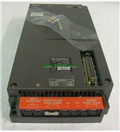
Product model: A0J2CPU-DC24
Name: Programmable Logic Controller
Brand: MITSUBISHI
Sort: Common Instructions Programming Manual
File language: English
Download link: MITSUBISHI A0J2CPU-DC24 Programming Manual
Multi axis positioning controller.
Program capacity: Max 60K step.
Input / output points: 1920 points.
The length of time required to execute the instruction, the length of the user''s program, the type of instruction, and the speed of the CPU execution are very significant,
Generally, a scanning process, the fault diagnosis time,
Communication time, input sampling and output refresh time is less,
The execution time is accounted for the vast majority of A0J2CPU-DC24 Common Instructions Manual A0J2CPU-DC24 Programming Manual A0J2CPU-DC24
The photoelectric coupler is composed of two luminous two extreme tubes and a photoelectric transistor.
Light emitting diode two: the input of a photo coupler and the change of electrical signal,
The light signal is generated by the light emitting diode, which is the same as the input signal A0J2CPU-DC24 Common Instructions Manual A0J2CPU-DC24 Programming Manual .
The working process of the input interface circuit: when the switch is closed, the diode light,
The transistor is then guided to the internal circuit and input signal under the irradiation of the light.
When the switch is off, the diode does not emit light, and the transistor is not on the way. Internal circuit input signal.
It is through the input interface circuit to the external switch signal into PLC internal can accept the digital signal A0J2CPU-DC24 Common Instructions Manual A0J2CPU-DC24 Programming Manual .
Photoelectric three levels: in the light of the light signal conduction, the degree of light signal and the intensity of the light signal.
The output signal has a linear relationship with the input signal in the linear operating region of the photoelectric coupler.
User program storage capacity: it is a measure of how much the user application can store the number of indicators.
Usually in words or K words as units. 16 bit binary number is a word,
Every 1024 words are 1K words. PLC to store instructions and data in words.
General logical operation instructions each account for 1 words. Timer / counter,
Shift instruction accounted for 2 words. Data operation instructions for 2~4. Type of input: DC leakage.
Input points: 64 points.
Input voltage: 12/DC24.
Input current: 2/5mA.
Connection mode: terminal row.
Common common point: 32.
Functional block diagram language is a kind of PLC programming language, which is similar to digital logic circuit.
The function module is used to represent the function of the module,
Different function modules have different functions.
Functional module figure programming language features: functional block diagram programming language is characterized by a functional module for the unit,
Analysis and understanding of the control scheme is simple and easy: function module is to use graphiccal form of expression,
Intuitive, for a digital logic circuit based on the design of the staff is very easy to master the programming;
Control system with complex scale and coomplex control logic,
Because the function module diagram can clearly express the function relation, the programming debugging time is greatly reduced A0J2CPU-DC24 Common Instructions Manual A0J2CPU-DC24 Programming Manual A0J2CPU-DC24 Common Instructions Manual A0J2CPU-DC24 Programming Manual .
Related products
MITSUBISHI
CPU unit
A0J2CPUR23
Input and output points: 480 points.
Pro
MITSUBISHI
CPU unit
A0J2CPUP23

Input and output points: 480 points.
Pro
MITSUBISHI
CPU unit
A0J2CPU
Input and output points: 480 points.
Pro
MITSUBISHI
CPU unit
A0J2CPU-DC24

Input and output points: 480 points.
Pro