 LK Automation Limited
Download Sort:
MITSUBISHI
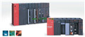
MITSUBISHI A0J2-62DA Manual A0J2-62DA User's Manual
Product model: A0J2-62DA
Name: D/A Converter Unit
Brand: MITSUBISHI
Sort: User's Manual
File language: English
Download link: MITSUBISHI A0J2-62DA User's Manual
Analog output DC4-20mA.
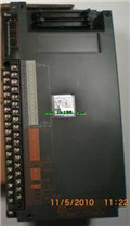
8 channel analog output module.
Ans series has now launched a dedicated 8 channel D/A components,
Both voltage output and current output can be provided.
In this way, the user system to provide a higher density of D/A features,
The same method is used to maintain the same output voltage or current output A0J2-62DA Manual A0J2-62DA User's Manual. Input type: DC input, positive common end A0J2-62DA
Input points: 16 points.
Enter the response time: 0.2ms below, below 1.5ms, 5ms below, 10ms the following.
Rated input voltage / current: DC12V/11mA.
Output form: transistor output, leakage type.
Output points: 16 points.
OFF leakage current: 0.1mA.
Output protection function: No.
Rated load voltage / current: DC12V/0.5A.
External connection: 1 line /1 line type A0J2-62DA Manual A0J2-62DA User's Manual.
According to the external connection mode and the external equipment input and output specifications,
Choose from a rich product lineup.
Finger protection through the upper part of the terminal,
The human body will not be exposed to live parts,
Therefore, the terminal station type remote I/O module can be directly mounted to the machine tool. Frequency selection: 100KHZ A0J2-62DA Manual A0J2-62DA User's Manual.
Number of channels: 2 channels.
Input signal: DC5/12/24, 2 to 5mA.
Counter: 100KPPS/1 with the highest frequency.
A1SD62, A1SD62D and A1SD62E are 2 channel high speed counter components for AnS series PLC.
They are improved in comparison with A1SD61 in the following ways: the density of channels.
In order to require a higher resolution and operating speed of the application to provide a higher count rate, reduce costs.
The instruction list programming language is a programming language similar to assembly language mnemonic,
As well as assembly language by the operation code and the number of operations.
In the case of the computer for the PLC handheld programmer compile user program.
At the same time, the programming language of the instruction list corresponds to the ladder diagram programming language,
In PLC programming software can be converted to each other. Figure 3 is the instruction sheet corresponding to the ladder diagram of figure 2PLC.
The characteristics of instruction table programming language is used to represent mnemonic operation function,
Easy to remember, easy to grasp;
In the handheld programmer on the keyboard using the mnemonic representation, easy to operate, can be programmed in computer;
There is a one-to-one correspondence between the ladder diagram and the ladder diagram. Its characteristics are basically consistent with the ladder diagram language.
Functional block diagram language is a kind of PLC programming language, which is similar to digital logic circuit.
The function module is used to represent the function of the module,
Different function modules have different functions.
Functional module figure programming language features: functional block diagram programming language is characterized by a functional module for the unit,
Analysis and understanding of the control scheme is simple and easy: function module is to use graphical form of expression,
Intuitive, for a digital logic circuit based on the design of the staff is very easy to master the programming;
Control system with complex scale and complex control logic,
Because the function module diagram can clearly express the function relation, the programming debugging time is greatly reduced.
The popularization and application of PLC programming has been developed rapidly in our country,
It has been widely used in all kinds of mechanical equipment and production process of electrical control devices,
All walks of life have emerged a large number of application of PLC transformation of the results of the equipment.
Understand the working principle of PLC, have the ability to design, debug and maintain the PLC control system,
Has become the basic requirements of modern industry for electrical technicians and engineering students.
PLC user program is designed according to the control sysstem of the process control requirements,
PLC programming language through the preparation of specifications, in accordance with the actual needs of the use of the function to design A0J2-62DA Manual A0J2-62DA User's Manual.
As long as the user caan master some kind of standard programming language,
To be able to use PLC in the control system,
To achieve a variety of automatic control functions A0J2-62DA Manual A0J2-62DA User's Manual.
Related products
MITSUBISHI
Analog output module
A0J2-62DA

2 channels.
Input resolution:-1000-100
MITSUBISHI
AC input / relay output module
A0J2-E56AR
Input points: 32 points.
Input voltage a
MITSUBISHI
DC input / transistor output module
A0J2-E28DT
Input points: 16 points.
Input voltage a
MITSUBISHI
Bidirectional thyristor output module
A0J2-E24S

Output points: 24 points.
Voltage: AC100