 LK Automation Limited
Download Sort:
MITSUBISHI
MITSUBISHI Q12DCCPU-CBL datasheet PDF catalog Q12DCCPU-CBL PDF datasheet
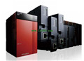
Product model: Q12DCCPU-CBL
Name: C语言CPU电缆
Brand: MITSUBISHI
Sort: PDF datasheet
File language: English
Download link: MITSUBISHI Q12DCCPU-CBL PDF datasheet
Meet safety standards: EN954-1 class 4, 13849-1 PL e ISO.
Safe input points: 1 points (2 input).
Start input points: 1.
Input type: N type (positive public end / negative public end input)
Safe output points: 1 points (3 output).
Spring clip terminal.
Additional security system.
Simply connect to the existing CC-LINK, you can add an independent security features Q12DCCPU-CBL datasheet PDF catalog Q12DCCPU-CBL PDF datasheet Q12DCCPU-CBL
Saving wiring by CC-link connection.
The wiring is not needed in particular to the condition monitoring of the safety relay module, and realizes the wiring of the cabinet and the other provinces.
Visualization of installation status.
Can monitor the safe output, as well as the safety input and the internal state of the relay, in the safety circuit to facilitate the identification of the reasons for the start Q12DCCPU-CBL datasheet PDF catalog Q12DCCPU-CBL PDF datasheet. Input and output points: 4096 points.
Input / output data points: 8192 points.
Program capacity: 124k.
Basic command processing speed (LD command) S:0.075.
The length of time required to execute the instruction, the length of the user''s program, the type of instruction, and the speed of the CPU execution are very significant,
Generally, a scanning process, the fault diagnosis time,
Communication time, input sampling and output refresh time is less,
The execution time is accounted for the vast majority of Q12DCCPU-CBL datasheet PDF catalog Q12DCCPU-CBL PDF datasheet.
The photoelectric coupler is composed of two luminous two extreme tubes and a photoelectric transistor.
Light emitting diode two: the input of a photo coupler and the change of electrical signal,
The light signal is generated by the light emitting diode, which is the same as the input signal.
The working process of the input interface circuit: when the switch is closed, the diode light,
The transistor is then guided to the internal circuit and input signal under the irradiation of the light.
When the switch is off, the diode does not emit light, and the transistor is not on the way. Internal circuit input signal.
It is through the input interface circuit to the external switch signal into PLC internal can accept the digital signal.
Photoelectric three levels: in the light of the light signal conduction, the degree of light signal and the intensity of the light signal.
The output signal has a linear relationship with the input signal in the linear operating region of the photoelectric coupler.
User program storage capacity: it is a measure of how much the user application can sstore the number of indicators Q12DCCPU-CBL datasheet PDF catalog Q12DCCPU-CBL PDF datasheet.
Usually in words or K words as units. 16 bit binary number is a word,
Every 1024 words are 1K words. PLC to store instructions and data in words.
General llogical operation instructions each account for 1 words Q12DCCPU-CBL datasheet PDF catalog Q12DCCPU-CBL PDF datasheet. Timer / counter,
Shift instruction accounted for 2 words. Data operation instructions for 2~4.
Related products
MITSUBISHI
C语言CPU电缆
Q12DCCPU-CBL
RS232 connector conversion cale round
MITSUBISHI
C language CPU
Q12DCCPU-V
Input / output points: 4096 points.
You