 LK Automation Limited
Download Sort:
MITSUBISHI
MITSUBISHI AD70 datasheet PDF catalog AD70 PDF datasheet
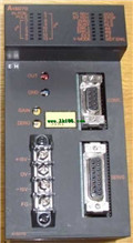
Product model: AD70
Name: Positioning module
Brand: MITSUBISHI
Sort: PDF datasheet
File language: English
Download link: MITSUBISHI AD70 PDF datasheet
Category: slave station.
Transfer speed: 125kbps/250kbps/500kbps/1Mbps.
Transmission line form: bus system.
Total distance: 125kbps:1000m/250kbps:800m/500kbps:480m/1Mbps:240m.
The maximum connection units: 32.
Total points: input + output <=2048 point.
MITSUBISHI PLC detection, fault diagnosis and display and other procedures AD70 datasheet PDF catalog AD70 PDF datasheet.
These procedures are relatively independent, generally in the basic completion of the program design and then add AD70
MITSUBISHI PLC protection and chain procedures.
Protection and chain is an indispensable part of the program, must be carefully considered.
It can avoid the control logic confusion caused by illegal operations. Axis of control: 3 axis linkage, 3 axis independence AD70 datasheet PDF catalog AD70 PDF datasheet.
Interpolation function: 3 axis linear interpolation, 3 axis arc interpolation.
A1SD75 series components show the MITSUBISHI in the manufacture and design of CNC, frequency converter,
Integrated technical experience in servo system and PLC.
These components have a wealth of features that are sufficient to meet the highest requirements in the application of positioning control.
A1SD75M, SCC net compatible controller, SSC network is the MITSUBISHI servo system control network AD70 datasheet PDF catalog AD70 PDF datasheet.
In this network, the MR-H-13, MR-J-B, and MR-J2 servo amplifiers can be connected to a controller via a network system,
The connection is replaced by a pulse sequence and a voltage signal. MELSECNET/10, MELSECNET/H coaxial.
Input voltage: AC100-240V.
How to choose MITSUBISHI PLC.
MITSUBISHI PLC options include the choice of MITSUBISHI PLC models, capacity, I/O module, power, etc..
MITSUBISHI PLC distribution I/O points and design MITSUBISHI PLC peripheral hardware circuit
Draw the I/O point of the PLC and the input / output device connection diagram or the corresponding table,
This part also can be carried out in second steps.
Design PLC peripheral hardware circuit.
Draw the electrical wiring diagram of the other parts of the system,
Including the main circuit and the control circuit does not enter the PLC, etc AD70 datasheet PDF catalog AD70 PDF datasheet. .
The electrical schematic diagram of the system compoosed of I/O PLC connection diagram and PLC peripheral electrical circuit diagram AD70 datasheet PDF catalog AD70 PDF datasheet.
So far the system''s hardware electrical circuit has been determined.
Related products
MITSUBISHI
Voltage output positioning control module
A1SD70
Axis of control: 1.
A1SD70 is a kind of
MITSUBISHI
Display module
AD57-S2
MITSUBISHI PLC hardware implementation
H
MITSUBISHI
Memory card interface module
AD59-S1

Memory card interface AD59-MEF, parall
MITSUBISHI
Type DC input module
QX70
Input points: 16 points.
Input voltage a