 LK Automation Limited
Download Sort:
MITSUBISHI
MITSUBISHI A1SJ71QE71N-T datasheet PDF catalog A1SJ71QE71N-T PDF datasheet
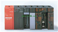
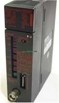
Product model: A1SJ71QE71N-T
Name: Network module
Brand: MITSUBISHI
Sort: PDF datasheet
File language: English
Download link: MITSUBISHI A1SJ71QE71N-T PDF datasheet
RS-232:1, RS-422/485:1.
Transmission speed: 0.3 ~ 19.2kpbs.
Computer connection function.
Printer / peripheral device connection, BASIC language function.
How to choose MITSUBISHI PLC.
MITSUBISHI PLC options include the choice of MITSUBISHI PLC models, capacity, I/O module, power, etc..
MITSUBISHI PLC distribution I/O points and design MITSUBISHI PLC peripheral hardware circuit
Draw the I/O point of the PLC and the input / output device connection diagram or the corresponding table,
This part also can be carried out in second steps A1SJ71QE71N-T datasheet PDF catalog A1SJ71QE71N-T PDF datasheet A1SJ71QE71N-T
Design PLC peripheral hardware circuit.
Draw the electrical wiring diagram of the other parts of the system,
Including the main circuit and the control circuit does not enter the PLC, etc A1SJ71QE71N-T datasheet PDF catalog A1SJ71QE71N-T PDF datasheet. .
The electrical schematic diagram of the system composed of I/O PLC connection diagram and PLC peripheral electrical circuit diagram.
So far the system''s hardware electrical circuit has been determined. Cable length: 5 meters.
Long distance CPU extension cable.
For QnA/ACPU/ motion control and GOT connection. 32: terminal line adapter 0.3mm2 (AGW22).8 slots.
Power supply unit A1SJ71QE71N-T datasheet PDF catalog A1SJ71QE71N-T PDF datasheet.
QnA series unit installation.
High speed access.
I/O points is an important indicator of PLC.
Reasonable selection of I/O points can not only satisfy the control requirements of the system,
And the total investment of the system is the lowest.
The input and output points and types of PLC should be determined according to the analog quantity and switch quantity of the controlled object,
Generally an input / output element to take up an input / output point.
Taking into account the future adjustment and expansion,
In general should be estimated on the total number of points plus the amount of spare 20%~30%.
When the programmer input programinto the user program memory,
Then CPU according to the function of the system (the system program memory to explain the compiler),
Translate the user program into PLC internally recognized by the user to compile the program.
Relay output interface circuit of PLC
Working process: when the internal circuit output digital signal 1,
There is a current flowing through, the relay coil has a current, and then the normally open contact is closed,
Provide load current and voltage.
When the internal circuit outtputs a digital signal 0, there is no current flowing through it,
The relay coil does not have a current, and the normally open contact is broken off,
A current or voltage that is discoonnected from the load A1SJ71QE71N-T datasheet PDF catalog A1SJ71QE71N-T PDF datasheet A1SJ71QE71N-T datasheet PDF catalog A1SJ71QE71N-T PDF datasheet.
It is through the output interface circuit to the internal digital circuit into a signal to make the load action or not action.
Related products
MITSUBISHI
Network module
A1SJ71LR21
3C-2V/5C-2V coaxial cale etween doule
MITSUBISHI
Network module
A1SJ71QLR21

3C-2V/5C-2V coaxial cale etween doule
MITSUBISHI
Network module
A1SJ71QE71N-B5T
Ethernet network module 10BASE-T / 10BAS
MITSUBISHI
Network module
A1SJ71QBR11
3C-2V/5C-2V coaxial cale etween the si