 LK Automation Limited
Download Sort:
MITSUBISHI
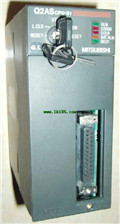
MITSUBISHI Q2ASCPU-S1 Hardware Manual Q2ASCPU-S1 User's Manual
Product model: Q2ASCPU-S1
Name: CPU Module
Brand: MITSUBISHI
Sort: Hardware User's Manual
File language: English
Download link: MITSUBISHI Q2ASCPU-S1 User's Manual
Input / output points: 4096 points.
Number of input and output elements: 8192.
Program capacity: 1000 K step.
Processing speed: 0.0095 s.
Program memory capacity: 4000 KB.
Support USB and network.
Support installed memory card.
Providing high speed communication between multiple CPU.
Shorten the fixed scan interrupt time, high precision device Q2ASCPU-S1 Hardware Manual Q2ASCPU-S1 User's Manual.
The minimum interval of the fixed period interrupt program is reduced to 100 s Q2ASCPU-S1
The high speed signal can be accurately obtained, which makes the contribution to the higher precision of the device.
High speed and high precision machine control by multi CPU.
By parallel processing of the linear and multi CPU high-speed communication (cycle 0.88ms) of the parallel control program, the high speed control Q2ASCPU-S1 Hardware Manual Q2ASCPU-S1 User's Manual.
Multi CPU high speed communication cycle and motion control synchronization, so it can achieve the maximization of computing efficiency.
In addition, the latest movement control CPU in performance is 2 times the previous model,
To ensure high speed and high accuracy of the machine control.Input and output points: 2048 points.
Input / output data points: 8192 points Q2ASCPU-S1 Hardware Manual Q2ASCPU-S1 User's Manual.
Program capacity: 92k.
Basic command processing speed (LD command) S:0.15.
The length of time required to execute the instruction, the length of the user''s program, the type of instruction, and the speed of the CPU execution are very significant,
Generally, a scanning process, the fault diagnosis time,
Communication time, input sampling and output refresh time is less,
The execution time is accounted for the vast majority of.
The photoelectric coupler is composed of two luminous two extreme tubes and a photoelectric transistor.
Light emitting diode two: the input of a photo coupler and the change of electrical signal,
The light signal is generated by the light emitting diode, which is the same as the input signal.
The working process of the input interface circuit: when the switch is closed, the diode light,
The transistor is then guided to the internal circuit and input signal under the irradiation of the light.
When the switch is off, the diode does not emit light, and the transistor is not on the way. Internal circuit input signal.
It is through the input interface circuit to the external switch signal into PLC internal can accept the digital signal.
Photoelectric three levels: in the light of the light signal conduction, the degree of light signal and the intensity of the light signal.
The output signal has a linear relationship with the input signal in the linear operating region of the photoelectric coupler.
User program storage capacity: it is a measure of how much the user applicattion can store the number of indicators Q2ASCPU-S1 Hardware Manual Q2ASCPU-S1 User's Manual.
Usually in words or K words as units. 16 bit binary number is a word,
Every 1024 words are 1K words. PLC to store instructions and data in words.
General llogical operation instructions each account for 1 words Q2ASCPU-S1 Hardware Manual Q2ASCPU-S1 User's Manual. Timer / counter,
Shift instruction accounted for 2 words. Data operation instructions for 2~4.
Related products
MITSUBISHI
Motion controller
Q170MSCPU-S1

Control axis: up to 16 axes.
Interpolati
MITSUBISHI
CPU unit
Q2ACPU-S1

Input and output points: 1024 points.
In
MITSUBISHI
CPU unit
Q2ASHCPU-S1
Input and output points: 1024 points.
In
MITSUBISHI
CPU unit
Q2ASCPU-S1
Input and output points: 1024 points.
In