 LK Automation Limited
Download Sort:
MITSUBISHI
MITSUBISHI MR-J3-11KT4 General-Purpose Interface Manual MR-J3-11KT4 INSTRUCTION MANUAL
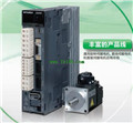
Product model: MR-J3-11KT4
Name: SERVO AMPLIFIER
Brand: MITSUBISHI
Sort: General-Purpose Interface INSTRUCTION MANUAL
File language: English
Download link: MITSUBISHI MR-J3-11KT4 INSTRUCTION MANUAL
MITSUBISHI motor universal AC servo amplifier MELSERVO-J3 series.
Rated output: 22.0kw.
Interface type: CC-Link communication type (built-in positioning function).
Power specification: three phase AC200V.
Positioning operation by setting position and rotational speed data in the positioning table and receiving the start signal from the main controller MR-J3-11KT4 General-Purpose Interface Manual MR-J3-11KT4 INSTRUCTION MANUAL MR-J3-11KT4
The setting of the position and speed of the positioning table, as well as the start and stop operation can be completed through CC-Link communication.
By using the MR-J3-D01 extension IO unit, the DI/O instruction can be used to select and locate the table.
(CC-Link can not be used for MR-J3-D01 communications).
With built-in positioning function of the servo amplifier, can be set through the CC-Link communications and speed data MR-J3-11KT4 General-Purpose Interface Manual MR-J3-11KT4 INSTRUCTION MANUAL. (corresponding to the CC-Link version: Ver.1.10)
Can be achieved through the CC-Link communications to start, stop and monitoring and other operations.
Serial communication reduce wiring.
Distributed servo control system can be built by CC-Link communication.
The parameters of unit MR-PRU03 (optional) the parameter setting, operation and monitoring more convenient MR-J3-11KT4 General-Purpose Interface Manual MR-J3-11KT4 INSTRUCTION MANUAL.
The servo amplifier can be used for speed control operation.
When the two stations are occupied, the speed can be set directly by the remote register. Drive: MR-H_ACN series built-in positioning function.
Rated output: 22KW.
In servo drive speed closed loop,
Rotor speed measurement accuracy is very important to improve the dynamic and static characteristics of the speed control loop.
In order to seek the balance between measurement precision and system cost, incremental photoelectric encoder is generally used as the speed measuring sensor,
The corresponding method is M/T velocity measurement.
Although the M/T measurement method has a certain measurement accuracy and a wide range of measurement,
But this method has its inherent defects,
Mainly includes: the measurement period must be detected at least one complete encoder pulse, limiting the minimum detectable speed.
2 control system ffor speed control of the timer switch is difficult to maintain synchronization,
Can not guarantee the accuracy of measurement in the situation where the speed change is largger MR-J3-11KT4 General-Purpose Interface Manual MR-J3-11KT4 INSTRUCTION MANUAL MR-J3-11KT4 General-Purpose Interface Manual MR-J3-11KT4 INSTRUCTION MANUAL.
Therefore, it is difficult to improve the speed tracking and control performance of servo drive by using the traditional speed loop design method.
Related products
MITSUBISHI
Universal pulse interface driver
MR-J3-DU55KA4
Drive unit 200VAC/400VAC level.
MITSUBIS
MITSUBISHI
CC-Link communication driver
MR-J3-15KT4

MITSUBISHI motor universal AC servo ampl
MITSUBISHI
SSCNET type III optical fiber communication driver
MR-J3-11KB4

MITSUBISHI motor universal AC servo ampl
MITSUBISHI
SSCNET type III optical fiber communication driver
MR-J3-100B4

MITSUBISHI motor universal AC servo ampl