Download Sort:
MITSUBISHI
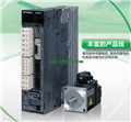
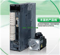
MITSUBISHI MR-J3-11KA Manual MR-J3-11KA INSTRUCTION MANUAL
Product model: MR-J3-11KA
Name: SERVO AMPLIFIER
Brand: MITSUBISHI
Sort: INSTRUCTION MANUAL
File language: English
Download link: MITSUBISHI MR-J3-11KA INSTRUCTION MANUAL
Drive: MR-H_ACN series CC-LINK features.
Rated output: 0.2KW.
The test system is composed of two parts, namely, the servo driver, the motor system and the host computer.
The host computer sends the speed command signal to the servo driver,
Servo drives start to run in accordance with the instructions MR-J3-11KA Manual MR-J3-11KA INSTRUCTION MANUAL.
In the course of operation, the running data of the servo system is collected by the host computer and the data acquisition circuit,
And carries on the preservation, the analysis and the display to the data MR-J3-11KA Because the motor is not loaded in this test system,
So compared with the previous two kinds of testing systems, the system has a relatively small volume,
And the measurement and control circuit of the system is relatively simple,
But it also makes the system can not simulate the actual operation of the servo drive MR-J3-11KA Manual MR-J3-11KA INSTRUCTION MANUAL.
Usually, such testing system is only used to test the rotational speed and angular displacement of the tested system under no-load condition,
And can not carry on the comprehensive and accurate test to the servo drive. MITSUBISHI motor universal AC servo amplifier MELSERVO-J3 series MR-J3-11KA Manual MR-J3-11KA INSTRUCTION MANUAL.
Rated output: 0.2kw.
Interface type: SSCNET type III fiber communication.
Special features: integrated driver security.
Power specification: single phase AC100V.
STO function as a security feature is added to the SSCNET III fiber communication type servo amplifier.
By using the STO function, the electromagnetic contactor used in the past to prevent the motor from accidentally starting is no longer needed.
SS1 functions can be realized by using the MR-J3-D05 security logic unit.
MR-J3-BS uses a full closed loop control system.
Compatibility with MR-J3-B.
MR-J3-BS installation, wiring and connectoors are the same as the MR-J3-B, so do not change the existing connection will be easy to MR-J3-B
Change to MR-J3-BS MR-J3-11KA Manual MR-J3-11KA INSTRUCTION MANUAL.
Security functions are connected to the CN8 interface through an external securityy circuit to increase the MR-J3-BS driver security MR-J3-11KA Manual MR-J3-11KA INSTRUCTION MANUAL.
Compatible full closed loop control system.
MR-J3-BS has a full closed loop control system version.
Related products
MITSUBISHI
SSCNET III connector kit
MR-J3BCN1

SSCNET III connector kit
MITSUBISHI
CC-Link communication driver
MR-J3-40T

MITSUBISHI motor universal AC servo ampl
MITSUBISHI
Integrated drive safety function driver
MR-J3-60BS4

MITSUBISHI motor universal AC servo ampl
MITSUBISHI
Encoder cable
MR-J3ENSCBL2M-H

The length of the line: 2m.
IP level: IP
