 LK Automation Limited
Download Sort:
MITSUBISHI
MITSUBISHI AJ71QC24N-R4 Modem Function Additional Version Manual AJ71QC24N-R4 User's Manual
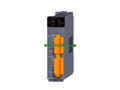
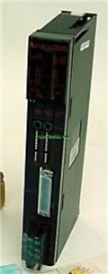
Product model: AJ71QC24N-R4
Name: Serial Communications Module
Brand: MITSUBISHI
Sort: Modem Function Additional Version User's Manual
File language: English
Download link: MITSUBISHI AJ71QC24N-R4 User's Manual
Axis of control: 2 axis linkage, 2 axis independence.
Interpolation function: 2 axis linear interpolation, 2 axis arc interpolation.
A1SD75 series components show the MITSUBISHI in the manufacture and design of CNC, frequency converter,
Integrated technical experience in servo system and PLC.
These components have a wealth of features that are sufficient to meet the highest requirements in the application of positioning control AJ71QC24N-R4 Modem Function Additional Version Manual AJ71QC24N-R4 User's Manual AJ71QC24N-R4
Up to 3 axis linkage operation,
In low cost motion control applications, this component can be used to control the operation of a multi - to 3 axis, which can be used to account for only one slot. Cable length 0.6m; used in A6TE2-16SRN.Multi axis positioning controller AJ71QC24N-R4 Modem Function Additional Version Manual AJ71QC24N-R4 User's Manual.
Program capacity: Max 60K step.
Input / output points: 1920 points.
The length of time required to execute the instruction, the length of the user''s program, the type of instruction, and the speed of the CPU execution are very significant,
Generally, a scanning process, the fault diagnosis time,
Communication time, input sampling and output refresh time is less,
The execution time is accounted for the vast majority of AJ71QC24N-R4 Modem Function Additional Version Manual AJ71QC24N-R4 User's Manual.
The photoelectric coupler is composed of two luminous two extreme tubes and a photoelectric transistor.
Light emitting diode two: the input of a photo coupler and the change of electrical signal,
The light signal is generated by the light emitting diode, which is the same as the input signal.
The working process of the input interface circuit: when the switch is closed, the diode light,
The transistor is then guided to the internal circuit and input signal under the irradiation of the light.
When the switch is off, the diode does not emit light, and the transistor is not on the way. Internal circuit input signal.
It is through the input interface circuit to the external switch signal into PLC internal can accept the digital signal.
Photoelectric three levels: in the light of the light signal conduction, the degree of light signal and the intensity of the light signal.
The output signal has a linear relationship with the input signal in the linear operating region of the photoelectric coupler.
User program storage capacity: it is a measure of how much the user application can store the number of iindicators AJ71QC24N-R4 Modem Function Additional Version Manual AJ71QC24N-R4 User's Manual.
Usually in words or K words as units. 16 bit binary number is a word,
Every 1024 words are 1K words. PLC to store instructions and data in words.
General llogical operation instructions each account for 1 words AJ71QC24N-R4 Modem Function Additional Version Manual AJ71QC24N-R4 User's Manual. Timer / counter,
Shift instruction accounted for 2 words. Data operation instructions for 2~4.
Related products
MITSUBISHI
Serial communication module (upgrade)
QJ71C24N-R4
RS-422/485.
2 channel.
Transmission spee
MITSUBISHI
Serial communication module
AJ71QC24-R4

RS-422 1 channel, RS-422/485 1 channel.
MITSUBISHI
Serial communication module
AJ71QC24-R2

RS-232 2 channel.
Transfer speed: 0.3-19
MITSUBISHI
Serial communication module
AJ71QC24
RS-232 1 channel, RS-422/485 1 channel.