 LK Automation Limited
Download Sort:
MITSUBISHI
MITSUBISHI AJ35PT-OPB-M1 Manual AJ35PT-OPB-M1 User's Manual
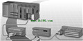
Product model: AJ35PT-OPB-M1
Name: I/O MODULE
Brand: MITSUBISHI
Sort: User's Manual
File language: English
Download link: MITSUBISHI AJ35PT-OPB-M1 User's Manual
Input voltage range: AC100-120V/AC200-240V.
Output voltage: DC5V.
Output current: 8A.
For Q4ARCPU.
The control module monitors the power supply, the error
CPU state,
And its own error state.
It sends out
Error signal a6raf and open the corresponding
Relay output.
I/O points is an important indicator of PLC AJ35PT-OPB-M1 Manual AJ35PT-OPB-M1 User's Manual.
Reasonable selection of I/O points can not only satisfy the control requirements of the system,
And the total investment of the system is the lowest AJ35PT-OPB-M1
The input and output points and types of PLC should be determined according to the analog quantity and switch quantity of the controlled object,
Generally an input / output element to take up an input / output point.
Taking into account the future adjustment and expansion,
In general should be estimated on the total number of points plus the amount of spare 20%~30% AJ35PT-OPB-M1 Manual AJ35PT-OPB-M1 User's Manual.
The following describes the centralized control system I/O points of the estimate. Applicable model: A95_GOT (-M3).Frequency selection: 100KHZ.
Number of channels: 2 channels.
Input signal: DC5/12/24, 2 to 5mA.
Counter: 100KPPS/1 with the highest frequency.
A1SD62, A1SD62D and A1SD62E are 2 channel high speed counter components for AnS series PLC AJ35PT-OPB-M1 Manual AJ35PT-OPB-M1 User's Manual.
They are improved in comparison with A1SD61 in the following ways: the density of channels.
In order to require a higher resolution and operating speed of the application to provide a higher count rate, reduce costs.
The instruction list programming language is a programming language similar to assembly language mnemonic,
As well as assembly language by the operation code and the number of operations.
In the case of the computer for the PLC handheld programmer compile user program.
At the same time, the programming language of the instruction list corresponds to the ladder diagram programming language,
In PLC programming software can be converted to each other. Figure 3 is the instruction sheet corresponding to the ladder diagram of figure 2PLC.
The characteristics of instruction table programming language is used to represent mnemonic operation function,
Easy to remember, easy to grasp;
In the handheld programmer on the keyboard using the mnemonic representation, easy to operate, can be programmed in computer;
There is a one-to-one correspondence between the ladder diagram and the ladder diagram. Its characteristics are basically consistent with the ladder diagram language.
Functional block diagram language is a kind of PLC programming language, which is similar to digital logic circuit.
The function module is used to represent the function of the module,
Different function modules have different functions.
Functional module figure programming language features: functional block diagram programming language is characterized by a functional module for the unit,
Analysis and understanding of the control scheme is simple and easy: function module is to use graphical form of expression,
Intuitive, for a digital logic circuit based on the design of the staff is very easy to master the programming;
Control system with complex scale and complex control logic,
Because the function module diagram can clearly express the function relation, the programming debugging time is greatly reduced.
The popularization and application of PLC programming has been developed rapidly in our country,
It has been widely used in all kinds of mechanical equipment and production process of electrical control devices,
All walks of life have emerged a large number of application of PLC transformation of the results of the equipment.
Understand the working principle of PLC, have the ability to design, debug and maintain the PLC control system,
Has become the basic requirements of modern industry for electrical technicians and engineering students.
PLC user program is designed according to the control system of tthe process control requirements,
PLC programming language through the preparation of specifications, in accordance with the actual needs of the use of the function to design AJ35PT-OPB-M1 Manual AJ35PT-OPB-M1 User's Manual.
As long as the user caan master some kind of standard programming language,
To be able to use PLC in the control system,
To achieve a variety of automatic control functions AJ35PT-OPB-M1 Manual AJ35PT-OPB-M1 User's Manual.
Related products
MITSUBISHI
DC input / transistor output module
AJ35PTF-56DT

DC input points: 32 points.
Input voltag
MITSUBISHI
AC input / silicon controlled output module
AJ35PTF-56AS

AC input points: 32 points.
Input voltag
MITSUBISHI
DC input module
AJ35PTF-32D
DC input points: 32 points.
Input voltag
MITSUBISHI
Melsecnet module
AJ35PTC-CNV

MELSECNET/MINI -S3 data link system, A