 LK Automation Limited
Download Sort:
MITSUBISHI
MITSUBISHI A985GOT-TBD Introductory Manual Manual A985GOT-TBD Operating Manual
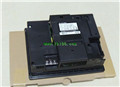
Product model: A985GOT-TBD
Name: touch screen
Brand: MITSUBISHI
Sort: Introductory Manual Operating Manual
File language: English
Download link: MITSUBISHI A985GOT-TBD Operating Manual
DC input points: 8 points.
Input voltage and current: 7mA, DC24V.
Response time: 10ms.
8 point /1 a public side.
Positive / negative sharing.
Output points: 8 points.
Output voltage and current: DC24V, 0.3A/1 point, 2.4A/1 common end.
Response time: 2ms.
8 point /1 a public side.
Output form: transistor output, leakage type A985GOT-TBD Introductory Manual Manual A985GOT-TBD Operating Manual.
34 point terminal station A985GOT-TBD
Number of stations: 2 stops.
According to the control requirements of the system, using the appropriate design method to design MITSUBISHI PLC program.
Procedures to meet the requirements of system control as the main line,
Write one by one to achieve the control function or the sub task of the program,
Gradually improve the functions specified by the system A985GOT-TBD Introductory Manual Manual A985GOT-TBD Operating Manual.
MITSUBISHI PLC detection, fault diagnosis and display and other procedures.
These procedures are relatively independent, generally in the basic completion of the program design and then add.
Hardware simulation method is to use a number of hardware equipment to simulate the generation of the signal,
The signals are connected to the input end of the PLC system in a hard wired way, and the timeliness is strong A985GOT-TBD Introductory Manual Manual A985GOT-TBD Operating Manual.
Software simulation method is in the MITSUBISHI PLC in the preparation of a set of simulation program,
The simulation provides the field signal, which is simple and easy to operate, but it is not easy to guarantee the timeliness.
Simulation of the process of debugging, debugging method can be used to segment, and the monitoring function of programmer. AnS, QnAS bus connection, the reader to write program 1 channel connection.
Input status and input information input from the input interface,
CPU will be stored in the working data memory or in the input image register.
And then combine the data and the program with CPU.
The result is stored in the output image register or the working data memory,
And then output to the output interface, control the external drive.
The response time of PLC is the interval between the time of the change of the external output signal of the PLC and the time of the change of the external output ssignal which is controlled by it,
Lag time, this is the time constant of the input circuit,
The time constant of the output circuit, the arrangement of the user statement and the usse of the instruction,
The cycle scan mode of PLC and the way of PLC to refresh the I/O and so on A985GOT-TBD Introductory Manual Manual A985GOT-TBD Operating Manual A985GOT-TBD Introductory Manual Manual A985GOT-TBD Operating Manual.
This phenomenon is called the I/O delay time effect.
Related products
MITSUBISHI
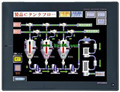
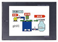
12 inch man machine interface
A985GOT-TBD
Series Name: A985GOT.
Size: 12 inches.
R
MITSUBISHI
12 inch man machine interface
A985GOT-TBA
Series Name: A985GOT.
Size: 12 inches.
R
MITSUBISHI
12 inch man machine interface
A985GOT-TBA-EU
Series Name: A985GOT.
Size: 12 inches.
R
MITSUBISHI
6 inch man machine interface
A951GOT-TBD
Series Name: A951GOT.
Size: 6 inches.
Re