LK Automation Limited
Download Sort:
MITSUBISHI
MITSUBISHI A975GOT-TBD-CH SW4D5C-GOTR-PACKE compatible Connection System Manual Manual A975GOT-TBD-CH User's Manual
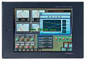
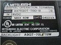
Product model: A975GOT-TBD-CH
Name: touch screen
Brand: MITSUBISHI
Sort: SW4D5C-GOTR-PACKE compatible Connection System Manual User's Manual
File language: English
Download link: MITSUBISHI A975GOT-TBD-CH User's Manual
Interface: RS422/485
Transmission distance: 500 meters
A1SJ71UC24-R2/R4/PR computer communication components can be relied on external intelligent devices such as computers and PLC for communication, the components are as follows:
Full / half duplex transmission,
4 special communication protocols,
No protocol and bidirectional mode,
Protocol selection switch function,
The optional baud rate, the highest 19 A975GOT-TBD-CH SW4D5C-GOTR-PACKE compatible Connection System Manual Manual A975GOT-TBD-CH User's Manual A975GOT-TBD-CH 2K,
Since the echo diagnostic test,I/O slots: 8 slots.
Could you install the power module.
Outline dimension: 420*130.
There are two types of extended floor,
A power module can be inserted, and the other one is not.
The choice of any type of substrate depends on the total DC5V current consumption and the power supply on the CPU main substrate A975GOT-TBD-CH SW4D5C-GOTR-PACKE compatible Connection System Manual Manual A975GOT-TBD-CH User's Manual.
If the total demand is less than the power output, no additional power supply,
Then you can choose a more economical expansion board.
Both ends of the main base plate of the CPU have an expansion interface, and can be used for extending the cable connection. Screw, 2 piece type terminal
Thermocouple Input module.
Number of channels: 8 channels A975GOT-TBD-CH SW4D5C-GOTR-PACKE compatible Connection System Manual Manual A975GOT-TBD-CH User's Manual.
Number of stations: 4 stops.
Station type: remote equipment station.
MITSUBISHI PLC online debugging.
On-line debugging is the process that will through the simulation debugging to further carry on the on-line unification to adjust.
On-line debugging process should be step by step,
From MITSUBISHI PLC only connected to the input device, and then connect the output device, and then connect to the actual load and so on and so on step by step.
If you do not meet the requirements, the hardware and procedures for adjustment.
Usually only need to modify the part of the program can be.
MITSUBISHI PLC hardware implementation
Hardware implementation is mainly for the control cabinet and other hardware design and field construction.
Design control cabinet and the operating table and other parts of the electrical wiring diagram and wiring diagram.
Electrical interconnection diagram of each paart of the design system A975GOT-TBD-CH SW4D5C-GOTR-PACKE compatible Connection System Manual Manual A975GOT-TBD-CH User's Manual.
According to the construction drawings of the site wiring, and carry out a detailed inspection.
Because the program deesign and hardware implementation can be carried out at the same time,
So the design cycle of the MITSUBISHI PLC control system can be greatly reduced A975GOT-TBD-CH SW4D5C-GOTR-PACKE compatible Connection System Manual Manual A975GOT-TBD-CH User's Manual.
Related products

MITSUBISHI
10 inch man machine interface
A975GOT-TBA-EU
Series Name: A975GOT.
Size: 10 inches.
R
MITSUBISHI
10 inch man machine interface
A975GOT-TBD-B
Series Name: A975GOT.
Size: 10 inches.
R