 LK Automation Limited
Download Sort:
MITSUBISHI
MITSUBISHI A68AD Manual A68AD User's Manual
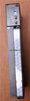
Product model: A68AD
Name: A/D Converter Module
Brand: MITSUBISHI
Sort: User's Manual
File language: English
Download link: MITSUBISHI A68AD User's Manual
GI fiber optic cable.
Dual loop for Q mode.
PC inter network (management station / station) / remote I/O network (remote control station).
How to choose MITSUBISHI PLC.
MITSUBISHI PLC options include the choice of MITSUBISHI PLC models, capacity, I/O module, power, etc..
MITSUBISHI PLC distribution I/O points and design MITSUBISHI PLC peripheral hardware circuit
Draw the I/O point of the PLC and the input / output device connection diagram or the corresponding table,
This part also can be carried out in second steps A68AD Manual A68AD User's Manual A68AD
Design PLC peripheral hardware circuit.
Draw the electrical wiring diagram of the other parts of the system,
Including the main circuit and the control circuit does not enter the PLC, etc A68AD Manual A68AD User's Manual. .
The electrical schematic diagram of the system composed of I/O PLC connection diagram and PLC peripheral electrical circuit diagram.
So far the system''s hardware electrical circuit has been determined. 3C-2V/5C-2V coaxial cable.
Double loop.
PC inter network (management station / common station) / remote I/O network (remote control station).
How to choose MITSUBISHI PLC.
MITSUBISHI PLC options include the choice of MITSUBISHI PLC models, capacity, I/O module, power, etc A68AD Manual A68AD User's Manual. .
MITSUBISHI PLC distribution I/O points and design MITSUBISHI PLC peripheral hardware circuit
Draw the I/O point of the PLC and the input / output device connection diagram or the corresponding table,
This part also can be carried out in second steps.
Design PLC peripheral hardware circuit.
Draw the electrical wiring diagram of the other parts of the system,
Including the main circuit and the control circuit does not enter the PLC, etc..
The electrical schematic diagram of the system composed of I/O PLC connection diagram and PLC peripheral electrical circuit diagram.
So far the system''s hardware electrical circuit has been determined. Analog channel: 16 channels.
Input / output (resolution): 0 ~ 4000.
Conversion speed: 100ms/16 channel.
Analog module installation.
Power supply: AC170V ~ 264V.
According to the control requirements of the system, using the appropriate design method to design MITSUBISHI PLC program.
Procedures to meet the requirements of system control as the main line,
Write one by one to achieve the control function or the sub task of the program,
Gradually improve the functions specified by the system.
MITSUBISHI PLC detection, fault diagnosis and display and other procedures.
These procedures are relatively independent, generally in the basic completion of the program design and then add.
Hardware simulation method is to use a number of hardware equipment to simulate the generation of the signal,
The signals are connected to the input end of the PLC system in a hard wired way, and the timeliness iis strong A68AD Manual A68AD User's Manual.
Software simulation method is in the MITSUBISHI PLC in the preparation of a set of simulation program,
The simulation provides the field signal, which is simple and easy to operate, but it is not easy too guarantee the timeliness A68AD Manual A68AD User's Manual.
Simulation of the process of debugging, debugging method can be used to segment, and the monitoring function of programmer.
Related products
MITSUBISHI
Quick connector plug
A6CON-P520
A pack of 20.
Applicale models:
AJ65SBT
MITSUBISHI
AD conversion module
A616DAV
16 channels.
Input resolution: -4000

MITSUBISHI
Extended bottom plate
A62B

2 slots.
To install the power supply.
Fo