 LK Automation Limited
Download Sort:
MITSUBISHI
MITSUBISHI A4UCPU Common Instructions Manual A4UCPU Programming Manual
Product model: A4UCPU
Name: Programmable Logic Controller
Brand: MITSUBISHI
Sort: Common Instructions Programming Manual
File language: English
Download link: MITSUBISHI A4UCPU Programming Manual
Remote I/O controller, coaxial cable.
How to choose MITSUBISHI PLC.
MITSUBISHI PLC options include the choice of MITSUBISHI PLC models, capacity, I/O module, power, etc..
MITSUBISHI PLC distribution I/O points and design MITSUBISHI PLC peripheral hardware circuit
Draw the I/O point of the PLC and the input / output device connection diagram or the corresponding table,
This part also can be carried out in second steps A4UCPU Common Instructions Manual A4UCPU Programming Manual A4UCPU
Design PLC peripheral hardware circuit.
Draw the electrical wiring diagram of the other parts of the system,
Including the main circuit and the control circuit does not enter the PLC, etc..
The electrical schematic diagram of the system composed of I/O PLC connection diagram and PLC peripheral electrical circuit diagram A4UCPU Common Instructions Manual A4UCPU Programming Manual .
So far the system''s hardware electrical circuit has been determined. Input type: DC input, positive public end / negative public end.
Input points: 32 points.
Enter the response time: 1.5ms the following.
Rated input voltage / current: DC24V/7mA.
External connection: 1 wire.
According to the external connection mode and the external equipment input and output specifications,
Choose from a rich product lineup A4UCPU Common Instructions Manual A4UCPU Programming Manual .
Finger protection through the upper part of the terminal,
The human body will not be exposed to live parts,
Therefore, the terminal station type remote I/O module can be directly mounted to the machine tool. Multiple CPU units for A3VTS multiplex system.
Modular: PLC is the basic components of a separate module.
Medium and large PLC used this way. Easy maintenance.
User program storage capacity: it is a measure of how much the user application can store the number of indicators.
Usually in words or K words as units. 16 bit binary number is a word,
Every 1024 words are 1K words. PLC to store instructions and data in words.
General logical operation instructions each account for 1 words. Timer / counter,
Shift instruction accounted for 2 words. Data operation instructions for 2~4.
Relay output interface circuit of PLC
Working process: when the internal circuit output digital signal 1,
There is a current flowing through, the relay coil has a current, and then the normally open contact is closed,
Provide load current and voltage.
When the internal circuit outputs a digital signal 0, there is no current flowing through it,
The relay coil does not have a current, and the normally open contact is broken off,
A current or voltage that is discoonnected from the load A4UCPU Common Instructions Manual A4UCPU Programming Manual A4UCPU Common Instructions Manual A4UCPU Programming Manual .
It is through the output interface circuit to the internal digital circuit into a signal to make the load action or not action.
Related products
MITSUBISHI
General purpose CPU
Q13UDHCPU
Input / output points: 4096 points.
Num
MITSUBISHI
Programmable logic controller CPU
R04ENCPU
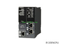
Operation control mode: stored procedure
MITSUBISHI
With Ethernet CPU
Q26UDEHCPU
Input / output points: 4096 points.
Num
MITSUBISHI
Programmable logic controller CPU
R32CPU
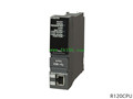
Operation control mode: stored procedure