 LK Automation Limited
Download Sort:
MITSUBISHI
MITSUBISHI A3ACPUP21 AD57 control Instructions Manual A3ACPUP21 Programming Manual
Product model: A3ACPUP21
Name: PLC
Brand: MITSUBISHI
Sort: AD57 control Instructions Programming Manual
File language: English
Download link: MITSUBISHI A3ACPUP21 Programming Manual
Using A6SIM-X64Y64 simulation I/O module in the system before the connection can be carried out to control the process of debugging.
The simulation unit consists of 16 blocks of 4 switches and 4 LED LEDs. Input type: DC input, positive public end / negative public end.
Input points: 16 points.
Enter the response time: 10ms the following A3ACPUP21 AD57 control Instructions Manual A3ACPUP21 Programming Manual A3ACPUP21
Rated input voltage / current: DC24V/7mA.
External connection: 1 wire.
Type of input and output terminal.
Using 2 pieces of structure of the terminal units, maintenance can be maintained in the same line under the condition of the replacement module. CPU connection program input device.
ACPU use. Output type: transistor output, drain type.
Output points: 16 points A3ACPUP21 AD57 control Instructions Manual A3ACPUP21 Programming Manual.
OFF leakage current: 0.1mA.
Output protection function.
Rated load voltage / current: DC24V/DC24V/0.1A.
External connection: 2 wire.
Fast connector type.
Simple wiring through quick connector.
Can be installed along the 6 direction.
MITSUBISHI PLC program simulation debugging
The basic idea of program simulation debugging is,
In order to facilitate the form of simulation to generate the actual state of the scene,
Create the necessary environmental conditions for the operation of the program A3ACPUP21 AD57 control Instructions Manual A3ACPUP21 Programming Manual.
Depending on the way the field signals are generated,
The simulation debugging has two forms of hardware simulation and software simulation. JEMANET (OPCN-1) interface unit from the station.
The response time of PLC is the interval between the time of the change of the external output signal of the PLC and the time of the change of the external output signal which is controlled by it,
Lag time, this is the time constant of the input circuit,
The time constant of the output circuit, the arrangement of the user statement and the use of the instruction,
The cycle scan mode of PLC and the way of PLC to refresh the I/O and so on.
This phenomenon is called the I/O delay time effect.
Input status and iinput information input from the input interface,
CPU will be stored in the working data memory or in the input image register A3ACPUP21 AD57 control Instructions Manual A3ACPUP21 Programming Manual.
And then combine the data and the program with CCPU A3ACPUP21 AD57 control Instructions Manual A3ACPUP21 Programming Manual.
The result is stored in the output image register or the working data memory,
And then output to the output interface, control the external drive.
Related products
MITSUBISHI
CPU unit
A3ACPUP21
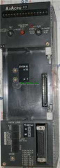
Input and output points: 2048 points.
In

MITSUBISHI
Moving CPU unit
A73CPUP21

Multi axis positioning controller.
Optic
MITSUBISHI
CPU unit
A3ACPUR21
Input and output points: 2048 points.
In