 LK Automation Limited
Download Sort:
MITSUBISHI
MITSUBISHI A1SJ71ID1-R4 Manual A1SJ71ID1-R4 User's Manual
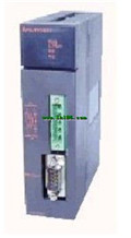
Product model: A1SJ71ID1-R4
Name: ID Interface Module
Brand: MITSUBISHI
Sort: User's Manual
File language: English
Download link: MITSUBISHI A1SJ71ID1-R4 User's Manual
Input type: DC input, positive public end / negative public end.
Input points: 16 points.
Enter the response time: 10ms the following.
Rated input voltage / current: DC24V/7mA.
External connection: 2 wire.
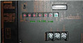
Type of input and output terminal.
Using 2 pieces of structure of the terminal units, maintenance can be maintained in the same line under the condition of the replacement module A1SJ71ID1-R4 Manual A1SJ71ID1-R4 User's Manual A1SJ71ID1-R4 Analog channel: 12 channels.
Input / output (resolution): 0 ~ 4000.
Conversion speed: 100ms/12 channel.
Analog module installation.
Power supply: AC170V ~ 264V.
According to the control requirements of the system, using the appropriate design method to design MITSUBISHI PLC program.
Procedures to meet the requirements of system control as the main line,
Write one by one to achieve the control function or the sub task of the program,
Gradually improve the functions specified by the system A1SJ71ID1-R4 Manual A1SJ71ID1-R4 User's Manual.
MITSUBISHI PLC detection, fault diagnosis and display and other procedures.
These procedures are relatively independent, generally in the basic completion of the program design and then add.
Hardware simulation method is to use a number of hardware equipment to simulate the generation of the signal,
The signals are connected to the input end of the PLC system in a hard wired way, and the timeliness is strong A1SJ71ID1-R4 Manual A1SJ71ID1-R4 User's Manual.
Software simulation method is in the MITSUBISHI PLC in the preparation of a set of simulation program,
The simulation provides the field signal, which is simple and easy to operate, but it is not easy to guarantee the timeliness.
Simulation of the process of debugging, debugging method can be used to segment, and the monitoring function of programmer. SI/QSI/H-PCF/ wide range H-PCF fiber optic cable.
Double loop.
PC inter network (management station / station) / remote I/O network (remote control station).
External power supply function.
How to choose MITSUBISHI PLC.
MITSUBISHI PLC options include the choice of MITSUBISHI PLC models, capacity, I/O module, power, etc..
MITSUBISHI PLC distribution I/O points and design MITSUBISHI PLC peripheral hardware circuit
Draw the I/O point of the PLC and the input / output device connection diagram or the corresponding table,
This part also can be carried out in second steps.
Design PLC peripheral hardware circuit.
Drraw the electrical wiring diagram of the other parts of the system,
Including the main circuit and the control circuit does not enter the PLC, etc A1SJ71ID1-R4 Manual A1SJ71ID1-R4 User's Manual. .
The electrical schematic diagram of the system compoosed of I/O PLC connection diagram and PLC peripheral electrical circuit diagram A1SJ71ID1-R4 Manual A1SJ71ID1-R4 User's Manual.
So far the system''s hardware electrical circuit has been determined.
Input points: 16 points.
Enter the response time: 10ms the following.
Rated input voltage / current: DC24V/7mA.
External connection: 2 wire.
Type of input and output terminal.
Using 2 pieces of structure of the terminal units, maintenance can be maintained in the same line under the condition of the replacement module A1SJ71ID1-R4 Manual A1SJ71ID1-R4 User's Manual A1SJ71ID1-R4 Analog channel: 12 channels.
Input / output (resolution): 0 ~ 4000.
Conversion speed: 100ms/12 channel.
Analog module installation.
Power supply: AC170V ~ 264V.
According to the control requirements of the system, using the appropriate design method to design MITSUBISHI PLC program.
Procedures to meet the requirements of system control as the main line,
Write one by one to achieve the control function or the sub task of the program,
Gradually improve the functions specified by the system A1SJ71ID1-R4 Manual A1SJ71ID1-R4 User's Manual.
MITSUBISHI PLC detection, fault diagnosis and display and other procedures.
These procedures are relatively independent, generally in the basic completion of the program design and then add.
Hardware simulation method is to use a number of hardware equipment to simulate the generation of the signal,
The signals are connected to the input end of the PLC system in a hard wired way, and the timeliness is strong A1SJ71ID1-R4 Manual A1SJ71ID1-R4 User's Manual.
Software simulation method is in the MITSUBISHI PLC in the preparation of a set of simulation program,
The simulation provides the field signal, which is simple and easy to operate, but it is not easy to guarantee the timeliness.
Simulation of the process of debugging, debugging method can be used to segment, and the monitoring function of programmer. SI/QSI/H-PCF/ wide range H-PCF fiber optic cable.
Double loop.
PC inter network (management station / station) / remote I/O network (remote control station).
External power supply function.
How to choose MITSUBISHI PLC.
MITSUBISHI PLC options include the choice of MITSUBISHI PLC models, capacity, I/O module, power, etc..
MITSUBISHI PLC distribution I/O points and design MITSUBISHI PLC peripheral hardware circuit
Draw the I/O point of the PLC and the input / output device connection diagram or the corresponding table,
This part also can be carried out in second steps.
Design PLC peripheral hardware circuit.
Drraw the electrical wiring diagram of the other parts of the system,
Including the main circuit and the control circuit does not enter the PLC, etc A1SJ71ID1-R4 Manual A1SJ71ID1-R4 User's Manual. .
The electrical schematic diagram of the system compoosed of I/O PLC connection diagram and PLC peripheral electrical circuit diagram A1SJ71ID1-R4 Manual A1SJ71ID1-R4 User's Manual.
So far the system''s hardware electrical circuit has been determined.
Related products
MITSUBISHI
Network module
A1SJ71QLP21S
SI/QSI/H-PCF/ wide H-PCF optical cale d
MITSUBISHI
Profibus interface module
A1SJ71PB92D
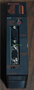
Availale network: Profius-DP.
Function
MITSUBISHI
MODBUS interface module
A1SJ71UC24-R2-S2
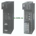
Data format: ASCII.
Data its: 7.
A1SJ71