 LK Automation Limited
Download Sort:
MITSUBISHI
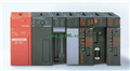
MITSUBISHI A1SJ71E71N3-T Hardware Manual A1SJ71E71N3-T User's Manual
Product model: A1SJ71E71N3-T
Name: Ethernet Interface Module
Brand: MITSUBISHI
Sort: Hardware User's Manual
File language: English
Download link: MITSUBISHI A1SJ71E71N3-T User's Manual
Input and output points: 512 points.
Input / output data points: 512 points.
Program capacity: 14K.
Basic command processing speed (LD command) s:0.20.
Each scanning process. Focus on the input signal sampling. Focus on the output signal to refresh.
Input refresh process. When the input port is closed,
Program in the implementation phase, the input end of a new state, the new state can not be read A1SJ71E71N3-T Hardware Manual A1SJ71E71N3-T User's Manual A1SJ71E71N3-T
Only when the program is scanned, the new state is read.
A scan cycle is divided into the input sample, the program execution, the output refresh.
The contents of the component image register are changed with the change of the execution of the program.
The length of the scan cycle is determined by the three A1SJ71E71N3-T Hardware Manual A1SJ71E71N3-T User's Manual.
CPU the speed of executing instructions.
Time of instruction.
Instruction count.
Due to the adoption of centralized sampling.
Centralized output mode.
There exist input / output hysteresis phenomena, i.e., the input / output response delay.
User program storage capacity: it is a measure of how much the user application can store the number of indicators.
Usually in words or K words as units A1SJ71E71N3-T Hardware Manual A1SJ71E71N3-T User's Manual. 16 bit binary number is a word,
Every 1024 words are 1K words. PLC to store instructions and data in words.
General logical operation instructions each account for 1 words. Timer / counter,
Shift instruction accounted for 2 words. Data operation instructions for 2~4. Analog channel: 8 channels.
Input / output (resolution): 0 ~ 4000.
Conversion speed: 100ms/8 channel.
Analog module installation.
Power supply: DC24V.
According to the control requirements of the system, using the appropriate design method to design MITSUBISHI PLC program.
Procedures to meet the requirements of system control as the main line,
Write one by one to achieve the control function or the sub task of the program,
Gradually improve the functions specified by the system.
MITSUBISHI PLC detection, fault diagnosis and display and other procedures.
These procedures are relatively independent, generally in the basic completion of the program design and then add.
Hardware simulation method is to use a number of hardware equipment to simulate the generation of the signal,
The signals are connected to the input end of the PLC system in a hard wired way, and the timeliness is strong.
Software simuulation method is in the MITSUBISHI PLC in the preparation of a set of simulation program,
The simulation provides the field signal, which is simple and easy to operate, but it is not easy too guarantee the timeliness A1SJ71E71N3-T Hardware Manual A1SJ71E71N3-T User's Manual A1SJ71E71N3-T Hardware Manual A1SJ71E71N3-T User's Manual.
Simulation of the process of debugging, debugging method can be used to segment, and the monitoring function of programmer.
Related products
MITSUBISHI
Ethernet module
A1SJ71E71N-B2
10BASE2.
PLC is introduced y the relay
MITSUBISHI
Melsecnet module
A1SJ71LP21GE
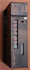
Using A1SJ71LP21 and A1SJ71BR11MELSECNET
MITSUBISHI
Modular
A1SJ71J92-S3
JEMANET OPCN-1 interface unit master s
MITSUBISHI
Computer communication module
A1SJ71UC24-R2
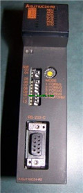
Interface: RS232C.
Transmission distance