LK Automation Limited
Download Sort:
MITSUBISHI
MITSUBISHI A1SCPU-S1 Common Instructions Manual A1SCPU-S1 Programming Manual
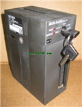
Product model: A1SCPU-S1
Name: Programmable Logic Controller
Brand: MITSUBISHI
Sort: Common Instructions Programming Manual
File language: English
Download link: MITSUBISHI A1SCPU-S1 Programming Manual
Cable length: 10 meters.
For QnA/A/FX (FX1, FX2, FX2C) CPU and GOT connection between.
For connection between FA-CNV_CBL and GOT.
For connection between FX-2PIF and GOT.
For connection between FX-422AW0 and GOT.
For serial communication module AJ71QC24 (N) -R4 and GOT connection between.
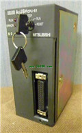
For connection between AJ65BT-G4-S3 and GOT A1SCPU-S1 Common Instructions Manual A1SCPU-S1 Programming Manual . Output type: transistor output, source A1SCPU-S1
Output points: 8 points.
OFF leakage current: 0.1mA.
Output protection function.
Rated load voltage / current: DC12V/DC24V/0.1A.
External connection: 1 wire.
According to the external connection mode and the external equipment input and output specifications,
Choose from a rich product lineup.
Finger protection through the upper part of the terminal,
The human body will not be exposed to live parts,
Therefore, the terminal station type remote I/O module can be directly mounted to the machine tool A1SCPU-S1 Common Instructions Manual A1SCPU-S1 Programming Manual . SI/QSI/H-PCF/ wide range H-PCF fiber optic cable.
Double loop.
PC inter network (management station / station) / remote I/O network (remote control station).
How to choose MITSUBISHI PLC.
MITSUBISHI PLC options include the choice of MITSUBISHI PLC models, capacity, I/O module, power, etc A1SCPU-S1 Common Instructions Manual A1SCPU-S1 Programming Manual . .
MITSUBISHI PLC distribution I/O points and design MITSUBISHI PLC peripheral hardware circuit
Draw the I/O point of the PLC and the input / output device connection diagram or the corresponding table,
This part also can be carried out in second steps.
Design PLC peripheral hardware circuit.
Draw the electrical wiring diagram of the other parts of the system,
Including the main circuit and the control circuit does not enter the PLC, etc..
The electrical schematic diagram of the system composed of I/O PLC connection diagram and PLC peripheral electrical circuit diagram.
So far the system''s hardware electrical circuit has been determined. PLC station distance: 2Km.
Cable type: GI-62.5/125.
The function of the MELSECNET interface module is to connect the main CPU PLC to the MELSECNET data communication system.
As long as the switch on the component to set,
Can determine the CPU PLC is as the main station or in situ station.
There are two modules available for selection: one is the connection of the optical cable network and the network of the coaxial cable.
For a ANSCPU, up to only a piece of interface components can be inserted, A2ASCPU can be inserted 2.
The popularization and application of PLC programming has been developed rapidly in our country,
It has been widely used in all kinds of mechanical equipment and production process of electrical control devices,
All walks of life have emerged a large number of application of PLC transformation of the results of the equipment.
Understand the working principle of PLC, have the ability to design, debug and maintain the PLC control system,
Has become the basic requirements of modern industry for electrical technicians and engineering students.
The instruction list programming language is a programming language similar to assembly language mnemonic,
As well as assembly language by the operation code and the number of operations.
In the case of the computer for the PLC handheld programmer compile user program.
At the same time, the programming language of the instruction list corresponds to the ladder diagram programming language,
In PLC programming software can be converted to each other. Figure 3 is the instruction sheet corresponding to the ladder diagram of figure 2PLC.
The characteristics of instruction table programming language is used to represent mnemonic operation funcction,
Easy to remember, easy to grasp;
In the handheld programmer on the keyboard using the mnemonic representation, easy to operate, can be programmed in computer;
There is a one-tto-one correspondence between the ladder diagram and the ladder diagram A1SCPU-S1 Common Instructions Manual A1SCPU-S1 Programming Manual A1SCPU-S1 Common Instructions Manual A1SCPU-S1 Programming Manual . Its characteristics are basically consistent with the ladder diagram language.
For QnA/A/FX (FX1, FX2, FX2C) CPU and GOT connection between.
For connection between FA-CNV_CBL and GOT.
For connection between FX-2PIF and GOT.
For connection between FX-422AW0 and GOT.
For serial communication module AJ71QC24 (N) -R4 and GOT connection between.
For connection between AJ65BT-G4-S3 and GOT A1SCPU-S1 Common Instructions Manual A1SCPU-S1 Programming Manual . Output type: transistor output, source A1SCPU-S1
Output points: 8 points.
OFF leakage current: 0.1mA.
Output protection function.
Rated load voltage / current: DC12V/DC24V/0.1A.
External connection: 1 wire.
According to the external connection mode and the external equipment input and output specifications,
Choose from a rich product lineup.
Finger protection through the upper part of the terminal,
The human body will not be exposed to live parts,
Therefore, the terminal station type remote I/O module can be directly mounted to the machine tool A1SCPU-S1 Common Instructions Manual A1SCPU-S1 Programming Manual . SI/QSI/H-PCF/ wide range H-PCF fiber optic cable.
Double loop.
PC inter network (management station / station) / remote I/O network (remote control station).
How to choose MITSUBISHI PLC.
MITSUBISHI PLC options include the choice of MITSUBISHI PLC models, capacity, I/O module, power, etc A1SCPU-S1 Common Instructions Manual A1SCPU-S1 Programming Manual . .
MITSUBISHI PLC distribution I/O points and design MITSUBISHI PLC peripheral hardware circuit
Draw the I/O point of the PLC and the input / output device connection diagram or the corresponding table,
This part also can be carried out in second steps.
Design PLC peripheral hardware circuit.
Draw the electrical wiring diagram of the other parts of the system,
Including the main circuit and the control circuit does not enter the PLC, etc..
The electrical schematic diagram of the system composed of I/O PLC connection diagram and PLC peripheral electrical circuit diagram.
So far the system''s hardware electrical circuit has been determined. PLC station distance: 2Km.
Cable type: GI-62.5/125.
The function of the MELSECNET interface module is to connect the main CPU PLC to the MELSECNET data communication system.
As long as the switch on the component to set,
Can determine the CPU PLC is as the main station or in situ station.
There are two modules available for selection: one is the connection of the optical cable network and the network of the coaxial cable.
For a ANSCPU, up to only a piece of interface components can be inserted, A2ASCPU can be inserted 2.
The popularization and application of PLC programming has been developed rapidly in our country,
It has been widely used in all kinds of mechanical equipment and production process of electrical control devices,
All walks of life have emerged a large number of application of PLC transformation of the results of the equipment.
Understand the working principle of PLC, have the ability to design, debug and maintain the PLC control system,
Has become the basic requirements of modern industry for electrical technicians and engineering students.
The instruction list programming language is a programming language similar to assembly language mnemonic,
As well as assembly language by the operation code and the number of operations.
In the case of the computer for the PLC handheld programmer compile user program.
At the same time, the programming language of the instruction list corresponds to the ladder diagram programming language,
In PLC programming software can be converted to each other. Figure 3 is the instruction sheet corresponding to the ladder diagram of figure 2PLC.
The characteristics of instruction table programming language is used to represent mnemonic operation funcction,
Easy to remember, easy to grasp;
In the handheld programmer on the keyboard using the mnemonic representation, easy to operate, can be programmed in computer;
There is a one-tto-one correspondence between the ladder diagram and the ladder diagram A1SCPU-S1 Common Instructions Manual A1SCPU-S1 Programming Manual A1SCPU-S1 Common Instructions Manual A1SCPU-S1 Programming Manual . Its characteristics are basically consistent with the ladder diagram language.
Related products
MITSUBISHI
CPU unit
A2USHCPU-S1
I/O points: 1024.
Processing speed: 0.09
MITSUBISHI
Extension cable
A1SC01B
Cale length: 0.055 meters.
Extending ca
MITSUBISHI
CPU unit
A1SCPU
Program memory capacity: 8k.
Input / out