 LK Automation Limited
Information sort
MITSUBISHI
A61RP MITSUBISHI Power module A61RP
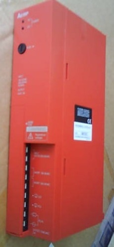
DC input points: 4 points.
Input voltage and current: 7mA, DC24V.
Input response time: 10ms.
4 point /1 a public side.
Positive pole sharing.
Output points: 4 points.
Output voltage and current: DC24V.
Output response time: 2ms.
4 point /1 a public side.
Output form: transistor output, leakage type A61RP.
24 point terminal station.
MITSUBISHI PLC protecction and chain procedures.
Protection and chain is an indispensable part of the program, must be carefully considered A61RP.
It can avoid the control logic confusion caused by illegal operations.
MITSUBISHI PLC initialization procedure. After MITSUBISHI PLC on power, the general need to do some of the initial operation,
In order to start making necessary preparations, to avoid the wrong operation of the system A61RP.
The main contents of the initialization program are: to some data area, counter and so on,
Data needed to restore some of the data area,
Set or reset some relays,
For some initial state display, etc..
MITSUBISHI PLC program simulation debugging
The basic idea of program simulation debugging is,
In order to facilitate the form of simulation to generate the actual state of the scene,
Create the necessary environmental conditions for the operation of the program MITSUBISHI A61RP.
Depending on the way the field signals are generated,
The simulation debugging has two forms of hardware simulation and software simulation MITSUBISHI A61RP.
Input voltage range: AC100-120V/AC200-240V.
Output voltage: DC5V.
Output current: 8A.
For Q4ARCPU.
The control module monitors the power supply, the error
CPU state,
And its own error state.
It sends out
Error signal a6raf and open the corresponding
Relay output MITSUBISHI A61RP.
I/O points is an important indicator of PLC.
Reasonable selection of I/O points can not only satisfy the control requirements of the system,
And the total investment of the system is the lowest.
The input and output points and types of PLC should be determined according to the analog quantity and switch quantity of the controlled object,
Generally an input / output element to take up an input / output point.
Taking into account the future adjusttment and expansion,
In general should be estimated on the total number of points plus the amount of spare 20%~30% A61RP.
The following describes the centralized control system I/O points of the estimate. Ethernet network module 10BASE-T / 10BASE5.
Related supply information